Author: John Kruse and Catherine Redmond Analog Devices Company
Tips :
(1) Normally, the activity of a simple pacemaker is not visible on the ordinary ECG chart, because very fast pulses are filtered out. However, those who have mastered pacing therapy can check the ECG curve to determine the presence of a pacemaker and evaluate its interaction with the heart.
(2) The pacing artifact signal of the implanted pacemaker can be from 2 mV to 700 mV, the duration is 0.1 ms to 2 ms, and the rise time is between 15 μs and 100 μs. Because electrical noise may be several times the amplitude of the pacing artifact signal, it is difficult to detect.
(3) Most implantable cardiac devices use H-field telemetry, which is an important source of noise.
(4) An algorithm is embedded in the ADAS1000 ECG analog front end, which can help identify pacing artifacts and display them on bar ECG drawings.
If a heart patient with a pacemaker implants an electrocardiogram, the doctor must be able to detect the presence and function of the pacemaker. Normally, the activities of purely implanted pacemakers are not visible on ordinary ECG charts, because of the low display resolution bandwidth (monitor / diagnostic bandwidth of 40 Hz / 150 Hz respectively), filtering out very fast pulses (typical Width is hundreds of microseconds). However, the pacemaker signal can be inferred from the change in the ECG waveform. An electrocardiogram is the electrical activity of the heart recorded by the ECG lead on the skin surface.
Detecting and identifying pacing artifact signals is very important because they indicate the presence of a pacemaker and can help assess its interaction with the heart. However, this artificial signal has a small amplitude, a narrow bandwidth, and a constantly changing waveform, so it is difficult to detect, especially when there is electrical noise that may be several times its amplitude. At the same time, pacing therapy has been very advanced, with a variety of pacing methods, from single-chamber pacing to three-chamber pacing. Pacemakers produce lead integrity pulses, ventilation per minute (MV) pulses, telemetry signals, and other signals, which may be mistaken for pacing artifacts, which complicates detection.
Using real-time pacemaker telemetry, pacing artifacts can be displayed in an ECG tape that is now less important. People who have experience in pacing therapy can watch this paper tape, and sometimes they can guess the type of pacing therapy used by the patient and determine whether the pacemaker is working properly.
In addition, all relevant medical standards require the display of pacing artifacts, but there are special requirements for the height and width of the captured pacing signal. Applicable standards include: American Society for Medical Instrument Promotion (AssociaTIon for the Advancement of Medical Instrumentation TIon, AAMI) specifications EC11: 1991 / (R) 2001 / (R) 2007 and EC13: 2002 / (R) 2007, and the International Electrotechnical Commission specification IEC60601- 1ed .3.0b: 2005, IEC 60601-2-25 ed.1.0b, IEC 60601-2-27 ed. 2.0: 2005 and IEC 60601-2-51 ed. 1.0: 2005.
Working principle of pacemaker
Implantable pacemakers (Figure 1) are usually light and small. They contain the necessary circuitry to monitor the electrical activity of the heart through implanted leads, stimulate the heart muscle as needed, and ensure a regular heartbeat. The pacemaker must be a low-power device, usually using a small battery with a life of 10 years. In 2010, the American Society of Engineers estimated that more than 400,000 pacemakers are implanted in patients every year (Reference 1).
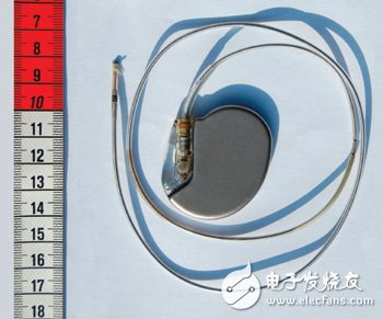
Figure 1 Implantable pacemakers are usually light and small
When unipolar pacing is used, the pacing lead includes the electrode at the tip of a single pacing lead, and the metal casing that wraps the pacemaker itself. On the skin surface, the amplitude of pacing artifacts generated in this way is hundreds of millivolts and the width is 2ms. But unipolar pacing is not commonly used.
Today, most pacing artifacts mainly come from bipolar pacing, which uses the electrodes at the tip of the pacing lead to excite the myocardium. The return electrode is a ring electrode very close to the tip electrode. The pacing artifacts generated by this type of lead are much smaller than unipolar pacing; the pulse on the skin surface can be as small as hundreds of microvolts, 25 μs in width, and the average signal value is 1 mV in height and 500 μs in width. If the detection direction fails to align with the pacing lead direction, then the amplitude of the pacing artifacts may also be much smaller.
The pulse width of many pacemakers can be set to a minimum of 25 μs, but the short pulse width setting is generally only used to test the threshold of the pacemaker in the electrophysiology laboratory. Limiting the lower limit to 100 μs can solve the problem of misdetecting MV and lead integrity (LV lead) pulses as effective pacing signals. These sub-threshold pulses are generally set between 10 μs and 50 μs.
There are different types of pacemakers for the pacing of a particular inner chamber of the heart. Single chamber pacing can be done in the right atrium or right ventricle. This type of pacemaker can be unipolar or bipolar. Biventricular pacing can provide pacing treatment for the right atrium and the right ventricle at the same time. Biventricular pacing can provide pacing treatment for the right and left ventricles at the same time; in addition, pacing is generally performed on the right atrium.
The dual-chamber pacing mode may be difficult to display normally for two main reasons. First, dual-chamber pacing may occur simultaneously, so it appears as a single pulse on the skin. Second, the position of the left ventricular lead is usually not on the same vector as the right ventricular lead, in fact the two will be perpendicular to each other. In general, the right atrium has the best display on lead aVF (one of the limb leads), while the right ventricle has the best display on lead II. Most ECG systems do not use a three-lead simultaneous detection circuit or algorithm, so the left ventricle becomes the most difficult lead to pick up. Therefore, sometimes it is best to detect one of the V leads.
Pacing artifact waveform
Most pacing pulses have very fast rising edges. The rise time measured at the output of the pacemaker is usually around 100 ns. When measured on the skin surface, the rise time will be slightly slower because of the inductance and capacitance of the pacing lead. Most pacing artifacts on the skin surface are on the order of 10 μs or lower. Because complex devices have built-in protection, the pacemaker may produce high-speed spikes, which will not affect the heart, but will affect the pacemaker detection circuit.
Figure 2 is an example of an ideal pacing artifact. The positive pulse has a fast rising edge. When the pulse reaches its maximum amplitude, it will follow a capacitive droop, and then a trailing edge will appear. Next, the pacing artifact will change the polarity of the charged portion of the pacing pulse. The reason for the need for a charging pulse is to keep the heart tissue in a net zero charge state; single-phase pulses can cause ions to gather around the electrode, creating a dc charge, which can cause deformation of the heart tissue.
The introduction of cardiac resynchronization devices adds more complexity to the detection and display of pacing artifacts. The pacing of these devices acts on the right atrium and the two ventricles. The pulses of the two ventricles may be very close, overlap, or appear almost simultaneously; the left ventricle may even pace before the right ventricle. Most devices now pace two ventricles at the same time, but studies have shown that adjusting the timing will produce higher cardiac output, which is beneficial for some patients.
It is not always possible to detect and display two pulses separately. In many cases, only one single pulse appears on the ECG electrode. If two pulses occur at the same time and the lead directions are opposite, the two pulses may cancel each other out on the skin surface. Although the probability of occurrence is low, it is conceivable that two ventricular pacing signals with opposite polarities appear on the skin surface. If the two pulses are offset by a small time difference, the final pulse shape may be very complicated.
Figure 3 shows the oscilloscope graph of the heart resynchronization device in a saline tank. This is a standard test environment for pacemaker certification, used to simulate the electrical conductivity of the human body. However, because the oscilloscope probe is close to the pacing lead, the amplitude is much higher than the skin surface, and the physiological saline solution exhibits a low impedance to the ECG electrode, so the noise is much smaller than that usually measured on the skin surface.
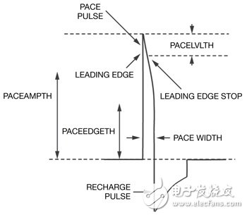
Figure 2 This is an example of an ideal pacing artifact. The positive pulse has a fast rising edge.
When the pulse reaches its maximum amplitude, it follows a capacitive droop, and then a trailing edge appears. Next, in the charged part of the pacing pulse, the pacing artifact changes polarity.
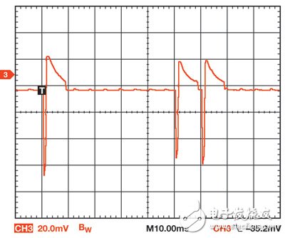
Figure 3 The oscilloscope shows the heart resynchronization device in a saline tank. This is a standard test environment for pacemaker certification.
The first, second, and third pulses (I to r) shown in the figure are atrium, right ventricle, and left ventricle pulses, respectively. The lead is placed in a saline tank, and its direction is optimized so that the pulse can be clearly seen. The negative pulse is pacing and the positive pulse is charging. The amplitude of the atrial pulse is slightly higher than the amplitude of the other two pulses because the atrial lead is slightly better than the ventricular lead; in fact, in the resynchronization device, all three pacing outputs are set to the same amplitude and width. For actual patients, the amplitude and width of each pacemaker lead are usually different.
Military Battery Pack has a strick requirements in working efficiency ,circuit protection ,cycle test ,working temperature and anti-impact.it refers to the Battery Pack which follows a strict standardard well known as international military standard or USA military stand ,in the other size ,the Military Battery pack is divided to Non-Rechargeable Military Battery Pack and rechargeable military battery pack.
Non-Rechargeable Battery:
BA-3030/U(LR20/FR20): 1.5V alkaline battery (and lithium iron disulfide);
BA-3042/U(LR14/FR14): 1.5V alkaline battery (and lithium iron disulfide);
BA-3058/U(LR6/FR6): 1.5V alkaline battery (and lithium iron disulfide);
BA-200/U: 6V primary zinc chloride battery;
BA-3200/U: 6V alkaline battery;
BA-5372/U: 6V/500mAh lithium manganese dioxide battery;
BA-5800/U: 6V/7.5Ah lithium sulfur dioxide battery;
BA-5390/U: 15V/30V,10Ah/20Ah lithium manganese dioxide battery;
BA-5590/U: 14V/28V,6.4Ah/12.8Ah lithium sulfur dioxide battery;
BA-3590/U: 15V/30V,7Ah/14Ah alkaline battery;
BA-3791/U: 15V,16Ah alkaline battery;
BA-3386/U: 15V,15Ah alkaline battery
Rechargeable battery:
BB-590/U: 12V/24V,2.4Ah/4.8Ah Ni-Cd battery;
BB-390/U: 12V/24V,4.5Ah/9Ah Ni-MMH battery;
BB-390B/U: 12V/24V,4.5Ah/9Ah Ni-MMH battery, with [LCD" display ;
BB-2590/U: 14.4V/28.8V,7.5Ah/15Ah, lithium ion battery, with [LCD" display;
TLI-9380E: 14.4V/15Ah, lithium ion battery;
BB-2590/U: 14.4V/28.8V,7.5Ah/15Ah, lithium ion battery, with [LCD" display and SMBUS ;
BB-2791: 14.4V/15Ah, lithium ion battery, with [LCD" display and SMBUS ;
TLI-718: 14.4V/5Ah, lithium ion battery.

Military Battery Pack
Military Battery Pack,Rechargeable Battery,Deep Cycle Battery,Rechargeable Military Battery Pack
YFJ TECHNOLOGY (HK) CO.,LIMITED , http://www.yfjpower.com