1 Introduction
The formation charge and discharge process of the battery is a complex chemical reaction process under the applied voltage, and the monitoring system is required to monitor the current and voltage value of the electrode plate and continuously adjust the charge and discharge parameters. Generally, a battery production plant has ten or even hundreds of chemical chargers running simultaneously under the control of their respective control systems, and these control systems are usually connected by RS485 / CAN bus, and realize master-slave communication with the upper computer through the serial port. With the increasing popularity of networking, it appears that the bottom layer is still connected by RS485 bus, and the Ethernet interface is set aside for direct connection with the corporate intranet. Here focuses on the realization of the Ethernet connection.
2 The composition and principle of the monitoring system
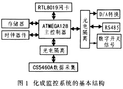
The system uses AVR as the main control core, and the CS5460A collects current and voltage values ​​in real time and sends them to the main controller. Based on real-time data, the main controller adopts a specific charging and discharging mechanism. The D / A converter TLC5615 outputs a voltage of 0 to 5 V through a voltage follower to control the external power supply circuit, and then performs different charging and discharging processes on the battery plate. RTL8019AS is selected as the network card, and the uIP protocol stack is embedded in the system, thereby realizing the Ethernet connection between the monitoring system and the PC. Its basic structure is shown in Figure 1.
3 System hardware design
3.1 Selection of main controller
Atmega128 adopts RISC structure, 128 Kb can be used in system programming / application programming Flash program memory, 4 Kb EEPROM, 4 Kb SRAM, abundant on-chip resources is very convenient to run a small operating system, such as μC / OS-Ⅱ can be embedded in IP protocol.
3.2 Data acquisition circuit design
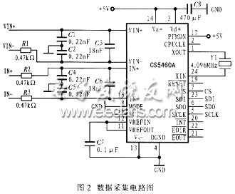
The CS5460A device is responsible for collecting the instantaneous value of the current and voltage of the plate. It is a CMOS single-chip power measurement device with an energy calculation engine that can measure instantaneous current, instantaneous voltage, instantaneous power, energy, and RMS current and RMS voltage. It uses the SPI interface to connect with the corresponding interface of the host, and has 4 I / O ports, which are chip select CS, data serial input SDI, data serial output SDO, and serial clock SCLK. In order to avoid external interference, it is isolated from the main controller by a photoelectric isolation device 6N137. The data acquisition circuit is shown in Figure 2. Among them, VIN +, VIN- is the voltage input terminal, used to detect the instantaneous voltage value in the charging and discharging circuit; IIN +, IIN- is the current input terminal, used to detect the instantaneous current. Feng controller external expansion parallel memory AM29F040B saves the sampling value in time, and external serial EEP-ROM AT24C04 saves the charge and discharge parameters.
3.3 Ethernet interface circuit design
RTL8019AS is a highly integrated 10 MB Ethernet controller, compatible with NE2000, supports 8-bit and 16-bit data buses; built-in 16 KB SRAM cache; can connect coaxial cables and twisted pairs, and can automatically detect the connected media The schematic diagram of its connection circuit is shown in Figure 3.
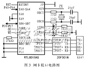
The JP pin of RTL8019AS determines the working mode of the network card. In the design, the JP pin is connected to a high level (VCC = + 5 V), that is, the jumper method is used, and the external EEPROM can be omitted at this time. The host computer accesses the Ethernet controller through the I / O mode. RTL80-19AS works in 8-bit mode, and its pin IOCS16B is grounded through a resistor. All control functions or data transmission are completed by accessing the register with an address offset of 00H to 1FH, so only five address lines (SA4 to SA0) is medium. In jumper mode, the I / O address of RTL8019AS is determined by pins IOS3 ~ IOS0. Connect all the corresponding pins of IOS3 ~ IOS0 to low level, SA8 and SA9 to high level, then the I / O base address of RTL8019AS is 300H. The 8-bit data line is SD0 to DS7. PL0 and PLl1 ground, using twisted pair connection. AEN is the address enable terminal, active low.
4 System software design
4.1 The composition of the system task module
The system tasks are divided into five modules, namely acquisition module, charge and discharge control module, RS485 bus communication module, Ethernet communication module, and fault detection module. Among them, the charge and discharge control module is based on the set process parameters, and the voltage and voltage holding time specified by the D / A input range from 0 to 5V; the fault detection module includes current fault, current interruption fault, overcurrent fault, program error fault, and power shortage Voltage failure and short-circuit failure.
4.2 Programming of Ethernet communication module
First write the driver of the network card to complete the task of digging the link layer in network communication. It provides three interface functions to the upper layer:
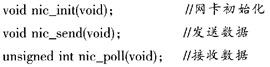
Because the system adopts a multi-task mechanism, a small operating system μC / OS-Ⅱ is embedded. The structure of uIP is very simple. The network card only needs to fill the received packet with uip_buf, set the length of uip_len to the packet length, and then check whether uip_len is greater than zero in the polling cycle of uIP. This program regards Ethernet communication as a task of μC / OS-Ⅱ. Part of the program code is as follows:

5 Conclusion
With an Ethernet interface, the control system can be directly connected to the upper network, but it needs to have Ethernet support that extends to the bottom of the plant. The embedded Web server of the device makes it possible to directly communicate information to the Internet and the outside world.
it is a two-color CCT temperature led strip. that can be changed color by an external specific controller.
on one strip has two color temperatures, which can meet different color temperature and scene requirements of the customer at the same time.
The led belt surface is lighter and more beautiful than the previous products,Suitable for home decoration lights,(Stairs, door frames, bar counters, wine cabinets, wardrobes, TV cabinets, DIY home decor...
it is more advantageous in the market.
Dimming LED Strip,LED Strip Dimmer,Dimmable LED Strip,LED Strip Light Dimmer
SHEN ZHEN SEL LIGHTING CO.,LTD , https://www.sel-lighting.com