introduction
According to data released by the World Health Organization, there are currently more than 30 million people blind in the world, and about 18% of them are Chinese. Aiming at the situation of impaired mobility of the blind, this article introduces a blind obstacle avoidance system based on ultrasonic phased array.
This article integrates the ultrasonic blind design and uses ultrasonic phased array technology to detect obstacles. The core control device STM32 is a 32-bit MCU based on the CORTEX kernel introduced by ST Company. Through its control of peripheral circuits, and its powerful signal processing capabilities, the detection of real obstacles and the judgment of the environment.
1 System composition and principle
This design uses the high-performance 32-bit MCU based on the CORTEX kernel launched by STMicroelectronics Co., Ltd., with STM32F103RBT6 as the core hardware. A plurality of ultrasonic probes are composed of an ultrasonic phased array according to certain rules, and a blind signal and obstacle avoidance function is completed by a signal transmission and recognition system composed of a chip, a probe and peripheral circuits. The block diagram of the working principle of the system is shown in Figure 1.
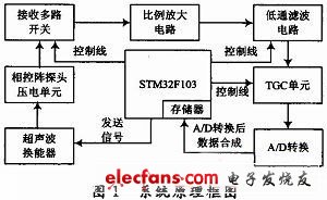
The system uses ultrasonic phased array to complete obstacle detection in the form of multiple transmissions and one reception. The specific scheme is as follows: The working frequency of the ultrasonic signal is 40 kHz. First, the STM32F103RBT6 MCU generates a square wave signal of 40 kHz. During operation, each probe sends 5 square wave signals in sequence according to a predetermined delay time. According to different delay time, the signal sent by the ultrasonic phased array can achieve focusing in different situations at 9 points in front. These 9 points are distributed in the left, center, and right directions in front of the ultrasound phased array, and there are 3 points in each direction: up, center, and down. The deflection angles in the left-right and up-down directions are set to 30 °. The depth of focus is 1.5 m. The signal takes about 8.8 ms from launch to return to the focus point. So after sending the signal, after 8 ms delay, open the switch of the receiving channel and start receiving the echo signal. Because the echo is relatively weak, the signal is first amplified to a signal that can be recognized by the microcontroller. After A / D conversion, it is stored, and then related signal analysis and processing work is carried out, so as to realize phased array scanning.
2 Introduction of ultrasonic phased array
The ultrasonic phased array transducer is composed of a plurality of independent piezoelectric wafers. According to certain rules and timing, each wafer unit is controlled and excited by an electronic system to adjust the focus position and focus direction. The most remarkable feature of phased array transducers is that they can flexibly, conveniently and effectively control the sound beam shape and sound pressure distribution. The sound beam angle, focal column position, focus size and position are continuously and dynamically adjustable within a certain range. Acoustic beam focusing can be achieved without an acoustic lens, so that the acoustic beam can be flexibly and effectively controlled to achieve area scanning detection; phased array technology can achieve ideal acoustic beam focusing; each array element is driven by the same amplitude voltage The actual sound field strength is much greater than conventional ultrasonic technology; it has obvious advantages in resolution, signal-to-noise ratio, and obstacle detection rate.
Scope of supply
Rating: Up to 200MVA
Voltage:Valve side voltage up to 1000VDC, Grid side voltage up to 220KV
Double star and double bridge
Applications:
The rectifier transformers are mainly used in the electrolysis processes for production of different kind of metals, such as aluminum electrolyzing, magnesium electrolyzing, copper electrolyzing, zinc electrolyzing and other more applications. The largest installed rectifier transformers are always for aluminum electrolysis with some transformer/rectifier combined units in parallel operation to get the required DC current.
Design:
The rectification method is normally known as double star or double bridge. Double star systems use an interphase transformer (IPT) and are usually applied as 6 or 12pulse units where high currents are required with very low nominal voltages. Double bridge system is applied as 6, 12, 24, 48 or 60pulse systems, as required to suit the harmonic mitigation and process stability requirements.
Duty
Electrolysis is normally a continuous process, but with a constant high loading and current harmonics.
Why SCOTECH
Long history- Focus on transformer manufacturing since 1934.
Technical support – 134 engineers stand by for you 24/7.
Manufacturing-advanced production and testing equipment, strict QA system.
Perfect service-The complete customer service package (from quotation to energization)
Rectifier Transformer,Bridge Rectifier Transformer,12 Pulse Rectifier Transformer,High Voltage Rectifier Transformer
Jiangshan Scotech Electrical Co.,Ltd , https://www.scotech.com