1 Introduction
With the increase in industrialization requirements, the development of distributed systems, and the need for communication between control equipment and monitoring equipment, monitoring systems designed with configuration software have gradually become popular. Now there are many configuration software, such as KingVieW (King Configuration), MCGS, WinCC and so on. KingView software is based on Microsoft Windows XP, NT / 2000 operating system. It has a friendly man-machine interface and powerful IO device port driving capability, and can communicate with various PLCs, smart meters, smart modules, boards, frequency converters, etc. in real time. Because the use of PLC and configuration software to communicate in an industrial site that detects a large number of analog quantities is bound to increase product costs. And the interface of the one-chip computer is abundant, can combine with A / D conversion module to finish the same work, and the system is reliable, the cost is low.
2 Serial communication method between Kingview and SCM
At present, the communication between Kingview and SCM is mostly done through dynamic data exchange (DDE) or through the development of communication drivers. DDE is a complete communication protocol on the Windows platform, through which Kingview exchanges data with other applications. But unreliable and non-real time. However, developing communication drivers yourself will bring design difficulties, increase the system development cycle, and the feasibility is not high. Kingview specializes in providing a serial port communication method with single-chip microcomputers, which can meet the needs of most systems.
3 Hardware interface circuit between PC and SCM
Figure 1 shows the connection circuit between the upper PC and the lower microcontroller 80C51. Both the PC and the single-chip computer have their own serial communication interfaces, but because the distribution of the PC and the single-chip computers is not centralized in the distributed system, RS-232 communication cannot be used for transmission, and only RS-485 can be used instead. RS-485 uses differential transmission signals with a maximum transmission distance of 1 219 m. The maximum transmission rate is 10 Mb / s. It has a strong ability to suppress the interference of two signal lines A and B that occur at the same time. When the two wires are twisted together, the interference signals coupled by the various distribution parameters of the communication can be evenly distributed to the two wires, so for the RS-485 differential transmission line, the twisted pair can be obtained Strong anti-interference ability. RS-485 adopts two-wire and four-wire balanced transmission method. Two-wire system can realize true multi-point two-way communication, but it needs to connect resistance (about 120 Ω) on the transmission line.

Due to the serial interface of 80C51 series single-chip STC89C52, the electrical characteristics of TTL and RS-485 are not consistent. STC89C52 cannot be directly connected with RS-485 and requires electrical conversion. Here the MAX485 of Maxim is used, and Figure 2 is its interface circuit.
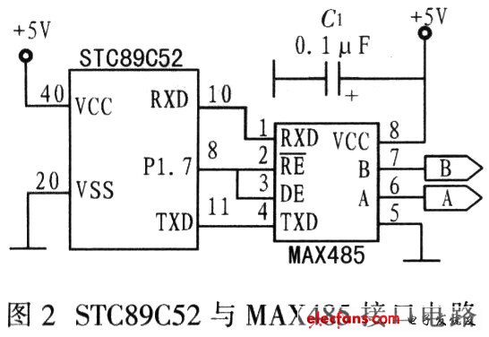
In Fig. 2, RE of MAX485 and P1.7 control of DE Nan STC89C52 one-chip computer. Because MAX485 works in a half-duplex mode, its transmission and reception are controlled by P1.7. When P1.7 is high level, the driver is enabled and the receiver is in high impedance state, and data can be sent at this time; and when P1.7 is low level. The receiver is enabled and the driver is in a high-impedance state, at which time data is received. In addition, because the COM port of the PC is a serial communication port based on RS-232. Its electrical characteristics are inconsistent with RS-485, so level conversion is also required.
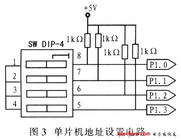
Figure 3 shows the single-chip microcomputer address setting circuit. The lower 4 bits of the P1 port of the single-chip microcomputer STC89C52 are used to set the local address. Up to 16 kinds of addresses can be set through the combination of 4 DIP switches. For example, when all the 4-position switches are off, the corresponding local address is 11 11. The lower MCU needs to set its own address before starting work, so that the lower single chip can obtain the local address during the power-on self-test.
For Iphone:
For Iphone8/X/XR/XS Max
Compabile Models:
For Samsung:
For Galaxy S6, For Galaxy S6 Edge, For Galaxy S6 Edge+,
For Galaxy S6 Active, For Galaxy S6 Duos, For Galaxy Note Edge,
For Galaxy S7, For Galaxy S7 Edge, For Galaxy Note 5
For Galaxy S8, For Galaxy S8 Plus, For Galaxy Note 8
For Galaxy S9,For Galaxy S9 Plus
For Sony:
For Xperia Z4V, For Xperia Z3V
For Google:
For Nexus 4, For Nexus 5, For Nexus 6, For Nexus 7
For MOTORALA:
For Moto Droid Turbo, For Moto Droid Turbo 2, For Moto Droid 5
For NOKIA:
For Lumia 920, For Lumia 928, For Nokia Lumia 93, For Lumia 950, For Lumia 950 XL, For Lumia 1020, For Nokia Lumia 1050, For Nokia Lumia 822, For Nokia Lumia 735
For HTC:
For HTC ONE MAX T6, For HTC Incredible 4G, For HTC ONE mini 2, For HTC Droid DNA
For LG:
For LG Nexus 4, For LG Nexus 5, For LG G Pro, For LG D1L, For LG LTE2
For Others:
For YotaPhone 2, For Elephone P9000
Guangzhou HangDeng Tech Co. Ltd , https://www.hangdengtech.com