Video synchronization separation circuit
Of course, the most commonly used circuit is the LM1881, which is very simple. The field synchronization time of the two RC devices is set, and the effect is very good.
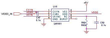
However, LM1881 has another feature, that is, it is expensive. When I first used it, it was 8 yuan, and now it seems to be 4 to 5 yuan. The replacement seems to be about the same price. Robbery! Use a circuit designed for someone else absolutely, but do n’t dare to use your own circuit.
It should be possible to design with a separate circuit. Was n’t the TV all transistors at first? The first one I designed with a separate circuit is N years old, and the devices are all pins. I remember looking for more than a dozen textbooks, monographs, circuit atlases, and I went to the library twice, but I could n’t find a circuit that could be used. Later, I found a circuit in a book published in the late 1970s, but it was used. It is a negative power supply, and it is changed to a positive power supply according to the principle. This is how it looks:
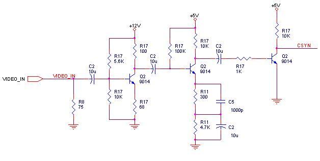
It is troublesome. The two power supplies should be reversed first, and then according to the principle of the capacitor discharge time. The voltage held by C2 makes the transistor Q2 only turn on when the synchronization arrives, and the TTL level will come out after another level of amplification. Very well. This circuit was drawn with OrCAD SDT3.34 at the time, and the files are not converted now, and can only be drawn once again.
When designing the synchronous separation circuit once again, it has entered the era of full SMD, and I went to find a lot of books. This time I still have a lot of papers in the journal online. However, I still found no directly usable circuits. Knowledge trash. Later, I thought of the old Toshiba two-piece TV. In the principle introduction of TA7680 / TA7698, there is a similar circuit. Take it and change it, change the N tube to P tube, and make a new synchronization separation circuit:
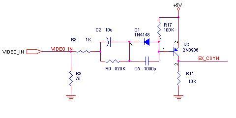
This circuit is much simpler and works well. However, I was very dissatisfied with it. One is that the electrolytic capacitor C2 and the diode D1 are too large, and the other is that there is no isolation. It is easy to move to other circuits without worry. When designing this circuit again, touch it on the basis of this circuit and change to a relatively simple circuit:
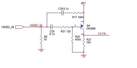
The principle is the same. Use the DC voltage accumulated at both ends of the larger capacitor to separate the sync head that changes greatly from the DC level point. This circuit boldly replaces electrolytic capacitors with 104 capacitors. It also works very well and the volume is greatly reduced. However, it was later found that the load change is not stable enough, and the CSYN output has clutter. What needs to be adjusted most here is the bias resistor R25. In the final application, either add a level of triode amplification at the back to shape the signal to eliminate the clutter that has not reached the TTL level; or add a level of radiation in front to isolate the impact of load changes.
No-encapsulated type NTC Temperature Sensor with the properties of sensitiveness, fast response, high temperature resistance, good appearance and protection has been used into oven, air conditioner, induction cooker, refrigerator and so on. Temperature range is from -30°C to 250°C.
No-Encapsulated Sensor,Oven Temperature Sensor,Air-Conditioner Sensor,Refrigerator Sensor
Feyvan Electronics Technology Co., Ltd. , http://www.fv-cable-assembly.com