1. Introduction At present, the vehicle-mounted technology is very mature. It is widely used in the anti-theft tracking of private cars, the dispatch control of logistics vehicles, the electric recruitment and security of taxis, the intelligent electronic stop sign for buses, etc., and its price is also Becomes very cheap. It can be bought in the market for a few hundred yuan [1]. Its core technology is GPS, and electronically is the soul of GPS. Only through it can the positioning of the vehicle be achieved. After the position of the vehicle is determined, the data can be sent to a third party through wireless transmission, so that the vehicle positioning can be achieved. This technology, we have established a model that can simulate the operation of the vehicle. It can determine the position of the vehicle through the GPS positioning system, send the vehicle's position information to the control center through the wireless transmission system, and send control instructions when there is a control center. Give the vehicle and let the vehicle reach the designated location, that is, a model of the "unmanned" vehicle system through GPS / GSM is established. Of course, this model is built on the highway. When the driver drives the highway, he can Commands are sent to the workstation through the control button. After the workstation is confirmed, the driver is notified, and then the vehicle enters the "unmanned" state. The operation of the car is determined by the control center. When the highway exit is reached, the control center will inform the driver and then will The driving right of the car is returned to the user, in order to prevent accidents, the user can also interrupt at any time Connection [2] Control Center.
This system simulates this model, using GSM as the data transmission medium, using the PC as the control center, replacing the vehicle with a car, simulating the operation of the vehicle on the campus, the GPS first sends the location information, and then the GSM takes the information It is transmitted to the PC and processed by the PC to display the position of the car on the map. The PC then issues instructions and transmits the instructions to the car via GSM. The car is executing instructions. 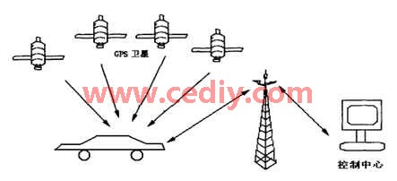
Figure 1. Unmanned driving control system model
2. System implementation theory overview
GPS currently has a total of 24 satellites in the space satellite constellation, including 21 working satellites and 3 spare satellites in orbit. Each satellite is equipped with 4 high-precision electronic clocks to provide high-precision time standards for GPS positioning. User equipment is mainly composed of GPS receiving hardware and data processing software, as well as a microprocessor and its terminal equipment [3].
GSM network is the most widely used wireless communication network in China. It has a fast transmission speed, a single data transmission price is cheap, does not occupy voice, and its two-way transmission performance can easily realize information collection and remote control of the collection station equipment, remote control, remote measurement and so on. Therefore, it is very reasonable to use GSM for wireless communication [4].
3. System implementation plan design In the design, Trimble ’s GPS module was used for car positioning, and two Siemens GSM modules were used for wireless data transmission of the car and PC, and the setting of the car part was completed by key input. Use LCD to display the current information, and use the serial port to communicate with the GSM module on the PC, and then display it on the electronic map based on the VB platform.
4. Hardware system design
4.1 Power supply voltage stabilization part The power supply of this system is 7.5V, and the working voltage of the single chip microcomputer is 5V, LM7805 is a 5V tributary voltage stabilization power supply chip. 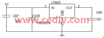
Figure 2 System power
4.2 GPS interface circuit Because the level of 51 series MCU is TTL level, and the GPS module is 3.3V power supply, so choose LM1117 as the power supply of GPS module, the communication part chose MAX3232 to convert the logic level of 3.3V to 232 level . 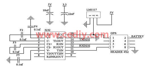
Figure 3 GPS interface circuit diagram 4.3 GSM interface circuit In the use of GSM module, its power supply range is very wide 7.5 ~ 24V, and its output level is 232 level so that this can lead to the serial communication data line.
4.4 GSM / GPS control part Because the MCU we use has only one serial port, which requires us to switch the serial port, we choose a relay, but because the drive current of the I / O port of the MCU is very small, the relay cannot work, so we use As a drive, ULN2003 is a reverse drive open circuit output Darlington, as shown in Figure 2, we use the single-chip tube current to drive the relay.
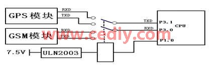
Figure 5 GSM / GPS control part
4.5 Motor control part For the motor control part, we adopt the inherited motor drive chip L298, its performance is relatively stable, and the drive current is large. The circuit diagram is as follows.
4.6 Display part In the display part, we use 12864 liquid crystal, in order to make the hardware structure simple, we use serial mode. 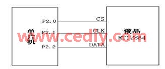
Figure 6 shows the part
5. Software implementation [5] 
Figure 7 Flow chart of the car control part
6. Conclusion This system realizes the simulation operation of GPS vehicle positioning system. Using GSM as the data transmission medium, the experimental car replaces the actual vehicle, and the PC is used as the vehicle control center to process the position information of the car and direct the movement of the car. Through the software test system, the position of the car is collected, and the command can also be received and executed by the car.
The author of this article innovates: The three technologies of single chip microcomputer, GPS and GPRS are integrated and applied reasonably and effectively to the vehicle monitoring system, realizing the real-time monitoring and dispatching of the vehicle, and improving the safety and working efficiency of the vehicle. The system has been running on the campus patrol car system of our school, saving nearly ten thousand yuan for the school. Practice has proved that the communication function of this system runs reliably and the design is reasonable.
Solar LED land lamp uses sunlight as the energy source, charges during the day and uses at night, does not need complex and expensive pipeline laying, can arbitrarily adjust the layout of lamps and lanterns, safe and energy-saving, pollution-free, stable and reliable without manual operation, saving electricity and maintenance. Solar LED street lamp is mainly composed of solar cell module (including bracket), LED lamp holder, control box (with controller, battery) and lamp pole.
Solar Led Street Light,Street Light Lamp,Solar Powered Street Lights,Solar Powered Led Street Lights
Yangzhou Heli Photoelectric Co., Ltd. , https://www.heli-eee.com