Abstract: With the development of China's transportation industry, vehicle tracking and monitoring is becoming more and more important in logistics and other industries. In the vehicle monitoring system, the vehicle cutting positioning terminal mostly uses GPS technology for positioning, and although GPS positioning has high positioning accuracy, there are defects of many blind spots. The location service based on the GSM network can just make up for the shortcomings of GPS positioning blind spots, which can effectively overcome the shortcomings of GPS positioning blind spots, so the positioning terminal integrates the advantages of GPS and GSM network positioning methods. Experimental results show that the positioning terminal can achieve accurate, real-time, all-weather, no blind spot positioning, which greatly improves positioning performance.
Keywords: GPS positioning; GSM positioning; positioning terminal; STK card
l Introduction With the expansion of China's urban construction scale and the increasing number of vehicles, GPS positioning monitoring systems have been widely used in transportation management, reasonable scheduling, and safety management. The application of GPS positioning technology provides specific real-time positioning capabilities for the navigation and positioning of vehicles, ships and other vehicles. The on-board GPS receiver enables the driver to know his specific location at any time. The GPS positioning information is sent to the monitoring and command center in the form of a short message, and the monitoring and command center can match the positioning information with the electronic map to grasp the specific location of each vehicle in time. However, when positioning GPS satellites, the GPS antenna requires a funnel-shaped 15 ° clearance angle to the sky and is greatly affected by clouds. For GPS tracking and navigation in transportation and other industries, vehicles need to be tracked in real time, so when GPS satellite signals are blocked by buildings and trees, GPS cannot perform normal navigation tracking and positioning.
The location service based on the GSM network can make up for this shortcoming of GPS positioning, and the GSM network covers a wide range of blind spots and can transmit location information to the far end. Based on the above considerations, this paper proposes a dual positioning terminal that integrates GPS and GSM network positioning. The terminal combines the advantages of GPS and GSM network positioning, and overcomes the shortcomings of GPS positioning blind spots and low GSM network positioning accuracy. , Performance has improved significantly.
2 System Overview
2.1 Positioning principle Global positioning system GPS (Global PosiTIoning System) is a new generation satellite navigation system in the United States, which can provide users with a global, all-weather, continuous satellite radio navigation system, which can provide real-time three-dimensional position, three-dimensional speed and High-precision time information. The GPS receiver converts its position and time information by receiving navigation information broadcast by any number of satellites in its line of sight.
Both China Mobile and China Unicom have opened location services. As long as you choose a SIM card that supports STK (SIM TOOL KIT), and the local network has opened the location service, you can get the location information through the STK command. The STK command is a set of commands for developing value-added services, a small programming language that allows the SIM-based user identification module SIM to run its own application software. STK card is a SIM card with STK function. The STK command will be slightly different depending on the manufacturer of the GSM module. For details, please refer to the manufacturer's "STK Command User Manual".
The GSM positioning method is similar to GPS positioning. The location of each mobile base station in the GSM network is known. The distance between the positioning terminal and the base station is determined according to the signal strength and other parameters during the communication between the positioning terminal and each base station. The position coordinates of the positioning terminal can be obtained from the distance from the base station to the positioning terminal.
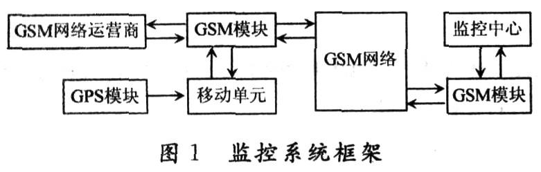
2.2 Introduction to the monitoring system The positioning system consists of a monitoring center and a vehicle positioning terminal. The GSM module in the vehicle positioning terminal not only communicates with the monitoring center through short messages, but also obtains location service information from the mobile operator through sTK. The positioning terminal sends GPS location information or positioning information obtained from the GSM network to the monitoring center in the form of a short message. The monitoring center integrates a GIS (Geographic InformaTIon System) map, and relies on the positioning information in the received short message to complete the matching of the terminal and the electronic map and some navigation instructions. The overall framework of the monitoring system is shown in Figure 1.
3 Design of vehicle dual positioning terminal hardware
3.1 Hardware composition of vehicle-mounted terminal Vehicle-mounted positioning terminal mainly includes GSM module, power module, voice module, LCD display module, GPS-OEM board. The positioning terminal uses a single chip microcomputer as the control chip. The GSM module uses Siemens' TC39I GSM engine module. In the car terminal, the TC39I GSM engine module not only obtains positioning information through the GSM network, but also communicates with the monitoring center in the form of short messages. The GPS-OEM board uses the ASHTECH ACl2OEM board, which is the professional-grade OEM board with the most complete functions, the smallest size, and the lowest power consumption produced by the American company THALES. ACl2 not only has GPS navigation timing, but also supports remote differential operation and has a tracking satellite-based enhancement system, as well as accurate carrier phase measurement performance. The GPS-OEM board is to make the main components of the GPS receiver into a large-scale integrated chip and integrate it on a circuit board. Its structure is shown in Figure 2.
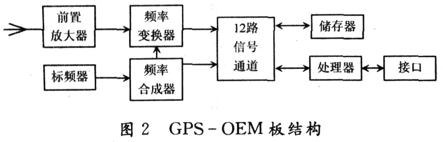
3.2 Working principle of GPS-OEM board GPS-OEM board is mainly composed of frequency converter, frequency converter, signal channel, microprocessor and storage unit. After completing the initial self-test, the GPS-OEM board will automatically receive the GPS RF signal from the antenna, convert it in a low-noise inverter, and change the L-band RF signal to a low-frequency signal, and then measure the GPS signal from the satellite through the signal channel To the propagation time of the receiving antenna, the navigation message sent by the GPS satellite is interpreted, and finally the central processor solves the three-dimensional coordinates, speed, time and other information of the measured point, and finally outputs the serial data through the I / O port.
The input and output of the GPS-OEM board all follow the serial communication protocol, and can output data information in the form of ASCII code conforming to the NMEA_0183 standard. The data structure is 8 data bits, 1 start bit, 1 stop bit, no parity bit. The user can initialize the GPS-OEM board by inputting sentences, setting data format, baud rate, and output sentence type information. The output sentence is to output various data information of GPS to the user. 3.3 Overall hardware design Both the GSM module and GPS-OEM board use serial data communication to have two serial ports with the MCU, which implement communication for UARTl and UARTO, respectively. The data transmission control is simple and reliable.
The 232 level conversion part is used for TTL-RS232 level conversion. The power supply module provides stable voltage output for the processor, GSM engine module and GPS module. The main function of the external control part is to accept external control commands such as manual alarms. The GPS-OEM board is used to provide data such as position information and time information. The single-chip computer regularly extracts the position information from the GPS-OEM board or through the GSM engine module to extract the position information from the GSM network operator through the STK card, and then through the GSM module short message The form sends the data to the monitoring center, the GSM module receives and sends short messages to the monitoring center. The received short message can be displayed on the LCD screen with a symbol easily understood by the user after being processed by the single-chip microcomputer, and can also be converted into a voice prompting the user through the language module. The hardware structure is shown in Figure 3.

Using the keyboard to roughly configure the measured longitude, latitude, and time can shorten the first positioning time and achieve rapid positioning. And the location information displayed can be changed through keyboard input, and the information that can be selected are: latitude and longitude, Beijing time, altitude, etc. Since the membrane key-type keyboard only needs one I / 0 port, it not only saves resources but also shortens the program amount, so the membrane key-type keyboard is selected in this design.
In the hardware design, because both the GSM module and the GPS module contain radio frequency modules, in order to avoid interference, the two modules should be as far away as possible. Can be placed on both sides of the PCB board or the two ends of the diagonal, practice has proved that this approach is effective.
4 Software design of positioning terminal System software design mainly includes initialization module, data processing module and man-machine dialogue module. Considering that GPS is more accurate than GSM positioning, GPS positioning is the main method while GSM positioning is the auxiliary. When the vehicle-mounted terminal is in a GPS blind spot area (such as a garage, a tree lined road, etc.) and cannot be located, GSM is used for positioning. The main program flow is shown in Figure 4.

4.1 Initialization module It is mainly to initialize the MCU, LCD module and ACl20 OEM board after power on. For MCU, set the serial port working mode, interrupt working mode, and baud rate; for the LCD display module, set the startup screen and display mode; for the ACl20 OEM board, you need to set the baud rate to successfully complete the serial communication.
4.2 Data processing module This module is mainly responsible for processing the data received from the GPS-OEM board and the data input from the keyboard. The refresh frequency of the output statement of the ACl20 OEM board is 1 Hz. In order to ensure the reliability and real-time performance of data transmission and improve the utilization rate of the MCU, the interrupt mode is used instead of the query mode.
4.3 Man-machine dialogue module This module mainly deals with keyboard input and display module operations. In the initial configuration process of the GPS-OEM board, it is necessary to configure the sentence setting of the OEM board according to actual needs. Another important task is to complete the data communication and processing between the MCU and the LCD module.
5 Conclusion Because GPS positioning is accurate and the GSM network covers a wide range of blind spots, the terminal is preferred to use GPS positioning. When GPS cannot be located, start GSM network positioning to locate the vehicle terminal, which can overcome the shortcomings of simple GPS positioning or GSM positioning, and The cost is lower. Practice has proved that this positioning terminal can enable GSM network positioning in places such as urban high-rise areas, tree-lined roads, garages, etc. where GPS satellite signals are lost and cannot be located, thereby improving the stability of positioning. It is a system that can provide real-time, accurate and interactive information, and can basically achieve accurate and blind spot-free positioning to ensure the effect of positioning. The system is completely feasible in terms of technology, economy and environmental protection.
Our factory provides 7" ,9" wired and wireless quad rear view mirror monitors.Really help you see the image behind your vehicle when you are reversing.
7/9/10.1 inch quad monitor has a pixel resolution of 800 x 480 /1024*600 and displayed is a sharp clear digital image. Monitor has 2 Channel Video Input; V1/V2 optional. PAL&NTSC for choose. Monitor automatically turns on and switch to Rear View Camera when reversing.
7-Inch TFT LCD quad screen Monitor with Built-in Wireless Receiver-- High resolution image and full color display.
surport 4 channes backup camera.l
Backup Camera Screen,Digital Quad Color Monitor,Quad Backup Camera System,Quad Backup Camera Monitor
Shenzhen Sunveytech Co.,LTD , https://www.sunveytech.com