Using MAX5438 and MAX749 to adjust LCD contrast
Introduce two commonly used methods to obtain adjustable negative bias voltage and their corresponding hardware and software design. Taking the practical circuits of MAX5438 and MAX749 as examples, the experimental data of the two circuits are given.
Keywords: negative voltage; liquid crystal display; contrast adjustment
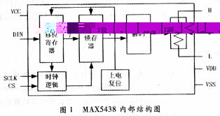
1.1 MAX5438 chip introduction MAX5438 is a 7-bit 128-step digital potentiometer produced by MAXIM. The internal structure is shown in Figure 1. It consists of a 7-bit shift register, a 7-bit data latch, a decoding module, a potentiometer, and control clock logic. The control signal of MAX5438 includes 3 input signals: chip select (
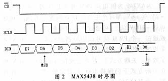
Since there is no EPROM inside the MAX5438, the position of the slider cannot be recorded, so at the beginning of the program, you must write a data to it as the starting value for later adjustment. This can be selected according to the actual situation of the circuit as a suitable value for the liquid crystal used as the initial value, which can greatly reduce the number of contrast adjustments. The starting value ranges from 00 to 7F, and these two values ​​correspond to the minimum and maximum output voltage, respectively. In the actual circuit shown in Figure 2, the input voltage of the MAX5438 is -12V provided by the MAX202, and the output voltage range is -9V to 0V. Due to the 128-step adjustment capability, the minimum value of the output voltage change is 9/128, which is about 0.1 V. For most liquid crystals, the negative bias voltage displays better at -8V to -9V, so the initial value is between 02 and 06. After entering the contrast adjustment menu, increase or decrease the initial value by pressing the key. Each time the key is pressed, the new value is sent to the MAX5438 to change its output voltage.
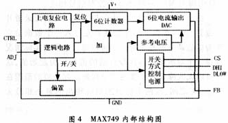
2.1 Functional Description of MAX749 MAX749 is an inverted PFM switching regulator. Input voltage from + 2V to + 6V can generate negative LCD bias voltage. The output voltage can reach above -100V, which can be adjusted by internal digital-to-analog converter, or by a PWM signal or potentiometer. The MAX749 uses a unique current control scheme that reduces quiescent current and improves efficiency. In shutdown mode, the quiescent current is only 15mA. The MAX749 maintains the set value of the DAC in the shutdown mode, simplifying software control. When the MAX749 generates a negative voltage, the external circuit can be driven by a P-channel MOSFET or a PNP transistor. The input voltage can be adjusted digitally or by a potentiometer. Its internal structure is shown in Figure 4.
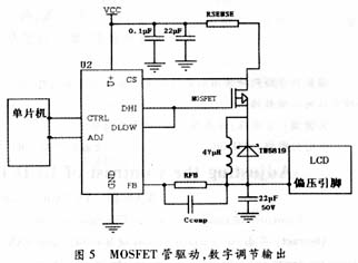
On the hardware, an RFB with an appropriate resistance value should be selected according to the liquid crystal used, so that the counter can provide a negative pressure greater than that required by the liquid crystal at the intermediate value of 32, but the RFB cannot be too large, otherwise RFB × 0.20 8μA will increase the accuracy of contrast adjustment accordingly. On the software, increase or decrease the number of pulses to be sent to the MAX 74 9 by pressing the button. Each time the key is pressed, a signal is sent to reset the MAX749, and then a corresponding pulse is sent to the ADJ through the pin of the microcontroller. In this way, in actual adjustment, the output voltage of the counter at 32 can be used as the starting point. The more the number of pulses, the lower the output negative pressure value, and the less the number of pulses, the more the output negative pressure value. High, to adjust the contrast of the LCD.
4 Phase Stepper Motors have been widely used in: X -Y plotters, CNC machines, sewing machines, ATMs, ticket machines, postal sorters, laboratory systems ,medical equipment, peripheral computer equipment`s,communication through laser and satellites, nuclear techniques, industrial robots, aeronautical and military equipment, etc.
4 phase stepper motor,4 pole stepper motor,Four phase stepper motor,4 phase unipolar stepper motor,Stepper motor with 5 wires
Shenzhen Maintex Intelligent Control Co., Ltd. , https://www.maintexmotor.com