Abstract: This applicaTIon note describes an ultra-low power microprocessor reset generator that is capable of operaTIng for decades from a single AA Lithium cell. Where conTInuous intermittent reset is desired, this relaxaTIon-oscillator circuit can provide adjustable pulse width and reset period. Typical operation producing 100µs pulses each second requires only 1µA current from a 1.8-5.5V supply. Formulas are provided for calculation of component values ​​for a wide range of pulse width and period.
When a processor-controlled device must be guaranteed to operate, designers often choose to reset the processor periodically rather than rely on a watchdog circuit. In low-power systems the periodic reset generator can consume a large part of the system current budget or may not be guaranteed to operate at low voltages.
This application note describes a low-power reset generator that generates a low going reset pulse of 100µS duration once per second, consumes less than 1µA and will operate from 1.8V to 5V with only slight variation of the output period.
Figure 1. This reset circuit consumes less than 1µA and delivers a 100-µsec-wide reset pulse every 1.3 sec.
The circuit is an adaptation of a normal relaxation oscillator with a differentiator and diode clamp on the output to generate the 100µS low going pulse. The pulse width can be adjusted by varying Cp or Rp and the polarity changed by repositioning D1. The period can be adjusted by varying R1 or C1.
The 350nA supply current, 1.8V-5.5V supply voltage range and SOT23 package make the MAX919 ideal for this application. Measurements for the complete circuit give operating currents of less than 1µA at 25 ° C, which would allow the circuit to operate from a single AA lithium cell for 250 years!
With careful component choice this circuit is able to generate periods from mS to minutes. To ensure good temperature stability R1 and Rp should be metal film and C1 and Cp should be NP0 type capacitors. Assuming a CMOS type input, high impedance and with a logic threshold of 30% of the supply rail, then the following formulas can be used to adjust the output pulse width and period:
Pulse width![]() 0.36 RpCp
0.36 RpCp
Period![]() 1.4 R1C1
1.4 R1C1
Measured pulse width:
1.308 seconds @ 4.5V
1.306 seconds @ 1.8V
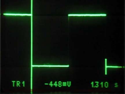
Figure 2. Comparator output; horizontal scale = 200mS / div, vertical scale = 1V / div, supply voltage = 4.5V, amplitude = 4.48Vp-p, period = 1.310 seconds.
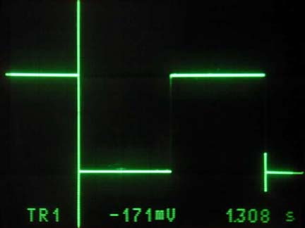
Figure 3. Comparator output; horizontal scale = 200mS / div, vertical scale = 500mV / div, supply voltage = 1.7V, amplitude = 1.7Vp-p, period = 1.308 seconds.
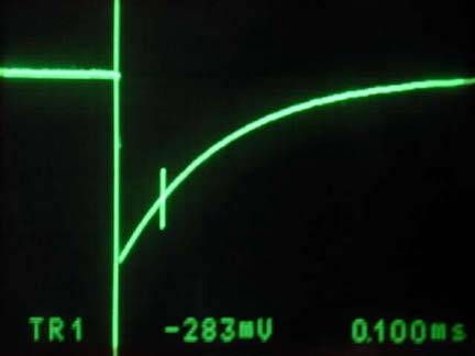
Figure 4. Pulse output; horizontal scale = 100µS / div, vertical scale = 1V / div, supply voltage = 4.5V, pulse width (30%) = 100µS.
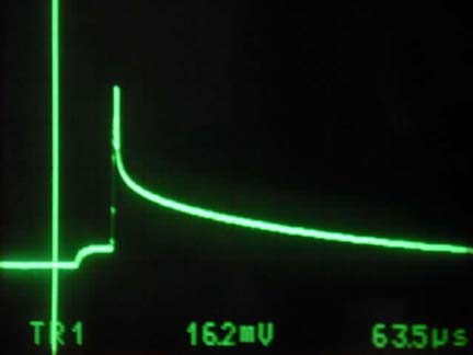
Figure 5. Clamp over shoot (at pulse output); horizontal scale = 50µS / div, vertical scale = 50mV / div, supply voltage = 4.5V, clamp over shoot = 162mV.
A similar version of this article appeared in the June 27, 2002 issue of EDN magazine.
When a processor-controlled device must be guaranteed to operate, designers often choose to reset the processor periodically rather than rely on a watchdog circuit. In low-power systems the periodic reset generator can consume a large part of the system current budget or may not be guaranteed to operate at low voltages.
This application note describes a low-power reset generator that generates a low going reset pulse of 100µS duration once per second, consumes less than 1µA and will operate from 1.8V to 5V with only slight variation of the output period.
Figure 1. This reset circuit consumes less than 1µA and delivers a 100-µsec-wide reset pulse every 1.3 sec.
The circuit is an adaptation of a normal relaxation oscillator with a differentiator and diode clamp on the output to generate the 100µS low going pulse. The pulse width can be adjusted by varying Cp or Rp and the polarity changed by repositioning D1. The period can be adjusted by varying R1 or C1.
The 350nA supply current, 1.8V-5.5V supply voltage range and SOT23 package make the MAX919 ideal for this application. Measurements for the complete circuit give operating currents of less than 1µA at 25 ° C, which would allow the circuit to operate from a single AA lithium cell for 250 years!
With careful component choice this circuit is able to generate periods from mS to minutes. To ensure good temperature stability R1 and Rp should be metal film and C1 and Cp should be NP0 type capacitors. Assuming a CMOS type input, high impedance and with a logic threshold of 30% of the supply rail, then the following formulas can be used to adjust the output pulse width and period:
Pulse width
Period
Measured pulse width:
1.308 seconds @ 4.5V
1.306 seconds @ 1.8V
Figure 2. Comparator output; horizontal scale = 200mS / div, vertical scale = 1V / div, supply voltage = 4.5V, amplitude = 4.48Vp-p, period = 1.310 seconds.
Figure 3. Comparator output; horizontal scale = 200mS / div, vertical scale = 500mV / div, supply voltage = 1.7V, amplitude = 1.7Vp-p, period = 1.308 seconds.
Figure 4. Pulse output; horizontal scale = 100µS / div, vertical scale = 1V / div, supply voltage = 4.5V, pulse width (30%) = 100µS.
Figure 5. Clamp over shoot (at pulse output); horizontal scale = 50µS / div, vertical scale = 50mV / div, supply voltage = 4.5V, clamp over shoot = 162mV.
A similar version of this article appeared in the June 27, 2002 issue of EDN magazine.
Low-Speed Vehicle,Low Speed Vehicles,Low Speed Electric Vehicles,Low Speed Neighborhood Electric Vehicles
Jinan Huajiang environmental protection and energy saving Technology Co., Ltd , https://www.hjnewenergy.com