
Overview of the MAX6960 stock price display system The MAX6960 is a graphic LED, dot matrix display driver, capable of driving 8x8 LED dot matrix. This application note uses 20 MAX6960s to drive 20 8x8 LED dot matrix units and displays the Maxim stock price. Windows software and microcontroller firmware can be easily modified to display your company's stock price and stock code. Hardware overview The application circuit includes five cascaded MAX6960EVKIT and one MAXQ2000-KIT. Figure 1 shows the system hardware block diagram of the program.
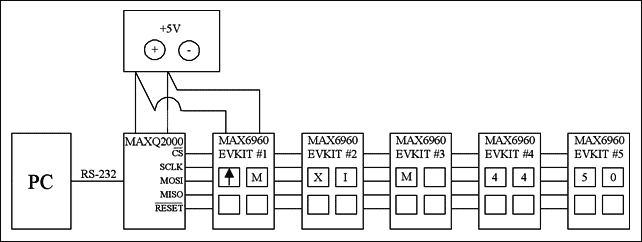
Figure 1. Hardware block diagram of stock price display system
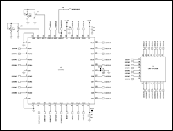
The MAX6960 EV kit contains four MAX6960s, four 8x8 LED dot matrix units, and all required passive components. The PCB layout has been verified. The circuit schematic of the MAX6960 evaluation board is shown in Figure 2. The MAXQ2000 is not installed on the MAX6960 evaluation board; the CS \, SCLK, DIN, DOUT, RESET \ and GND of the MAXQ2000 evaluation board need to be connected to the first MAX6960 evaluation board. The other four MAX6960 evaluation boards are cascaded with the first MAX6960 evaluation board. In addition, the + 5V pad of the first MAX6960 EV kit must be connected to a + 5V power supply capable of delivering 5A. Table 1 shows the jumper settings required when using five cascaded MAX6960 EV kits.
More detailed schematic (PDF, 495kb)
Figure 2. Schematic of the MAX6960 EV kit (6 pages-1 page)
Table 1. Cascade 5 MAX6960 evaluation boards
| MAX6960 EV kit # 1 | MAX6960 EV kit # 2 | MAX6960 EV kit # 3 | MAX6960 EV kit # 4 | MAX6960 EV kit # 5 |
| JU1: (2-3) | JU1: (2-3) | JU1: (2-3) | JU1: (2-3) | JU1: (2-3) |
| JU2: (2-3) | JU2: (2-3) | JU2: (2-3) | JU2: (2-3) | JU2: (2-3) |
| JU3: (1-2) | JU3: (2-3) | JU3: (2-3) | JU3: (2-3) | JU3: (2-3) |
| JU4: (2-3) | JU4: (2-3) | JU4: (2-3) | JU4: (2-3) | JU4: (2-3) |
| JU5: (2-3) | JU5: (2-3) | JU5: (2-3) | JU5: (2-3) | JU5: (2-3) |
| JU6: (1 only) | JU6: (1 only) | JU6: (1 only) | JU6: (1 only) | JU6: (1-2) |
| JU7: (2-3) | JU7: (2-3) | JU7: (2-3) | JU7: (2-3) | JU7: (2-3) |
| JU8: (2-3) | JU8: (2-3) | JU8: (2-3) | JU8: (2-3) | JU8: (2-3) |
| JU9: (1-2) | JU9: (2-3) | JU9: (2-3) | JU9: (2-3) | JU9: (2-3) |
| JU10: (2-3) | JU10: (2-3) | JU10: (2-3) | JU10: (2-3) | JU10: (2-3) |
| JU11: (2-3) | JU11: (2-3) | JU11: (2-3) | JU11: (2-3) | JU11: (2-3) |
| JU12: (OPEN) | JU12: (SHORT) | JU12: (SHORT) | JU12: (SHORT) | JU12: (SHORT) |
| JU13: (1-2) | JU13: (2-3) | JU13: (2-3) | JU13: (2-3) | JU13: (2-3) |
| JU14: (1 only) | JU14: (1-2) | JU14: (1-2) | JU14: (1-2) | JU14: (1-2) |
| JU15: (1-2) | JU15: (1 only) | JU15: (1 only) | JU15: (1 only) | JU15: (1 only) |
| JU16: (1-2) | JU16: (1-2) | JU16: (1-2) | JU16: (1-2) | JU16: (1-2) |
| JU17: (1 only) | JU17: (1-2) | JU17: (1-2) | JU17: (1-2) | JU17: (1-2) |
Note: Bold text indicates that the default settings have been changed.
The MAXQ2000 evaluation board contains the complete software, hardware, sample code, and documentation required for designing with the MAXQ2000 microcontroller. See the data sheet for the MAXQ2000-KIT schematic diagram. Firmware Overview The sample MAX-IDE assembler file in Firmware.Zip allows the MAXQ2000 to communicate with the MAX6960 through the SPI interface. When the MAXQ2000 uses a 16MHz system clock, the SPI serial clock is 2.5MHz. Table 2 shows the initialization of all MAX6960 SPI / GPIO operations after power-up.
Table 2. Initializing all MAX6960 SPI / GPIO operations after power-up
| Step | OperaTIon | Register Address | DescripTIon |
| 1 | GPI RESET \ | N / A | RESET \ was held low for 2.5ms after power-up to properly apply power to all five MAX6960 devices while power is stable. RESET \ was then driven high for 100ms. |
| 2 | SPI: 16-bit address mode write | Panel ConfiguraTIon Register (0x0D) | Sets: iColor to bicolor, 1-bit per pixeli Take all MAX6960 devices out of shutdown |
| 3 | SPI: 16-bit address mode write | Global Driver Devices Register (0x0E) | Sets: iNumber of devices to 20. |
| 4 | SPI: 16-bit address mode write | Global Driver Rows Register (0x0F) | Sets: iNumber of rows to 2. |
| 5 | Delay | N / A | Adds a required 450ms delay after steps 1 through 4 above. All the MAX6960 devices require this TIme to properly configure themselves. |
| 6 | RS-232 serial COM port | N / A | Waits for stock quote bytes to be sent from the Windows program to the MAXQ2000 through the RS-232 serial COM port. |
The data format of the RS-232 serial COM port is:
XXXU567.89X
X = Byte1 (Factory use only)
X = Byte2 (Factory use only)
X = Byte3 (Factory use only)
U = Byte4 (Stock Quote: Up, Down, or No Change Indicator)
5 = Byte5 (Hundreds Digit: 1xx.xx)
6 = Byte6 (Tens Digit: x1x.xx)
7 = Byte7 (Ones Digit: xx1.xx)
8 = Byte8 (Tenths Digit: xxx.1x)
9 = Byte9 (Hundredths Digit: xxx.x1)
X = Byte10 (Factory use only)
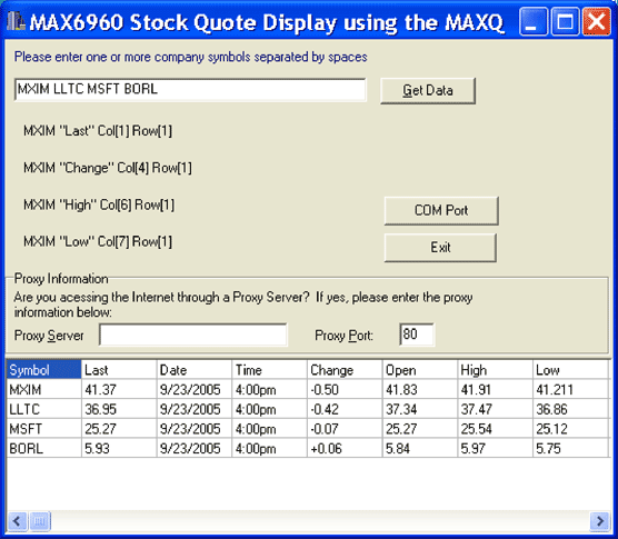
Figure 3. The Windows program obtains the stock price of MXIM via the Internet
outdoor power supply, waterproof product, it include 12 volt dc outdoor power supply and 24vac outdoor power supply.
Our special design: simple push-pull open housing , large space, convenient installation, laser printing OEM Logo. Waterproof rate is IP65.
Features:
Simple Open Housing:Push-Pull Way.
Fixation:The Gourd type
On the Bottom:LED indicator for PSU working condition
Space Large,convenient installation
Laser Printing OEM Logo
Glass fiber board, big transformer, 2A enough power.
Fully Surface design style housing, suitable for wet, dry, damp locations
4 times aging test
Comply with IP65 standard
Protection: short-circuit,over-load,over-voltage ,over current ,
over-temperature protection
3 years warranty
Product application:
Application to CCTV cameras, indoor and outdoor cameras, monitoring equipment power supply, alarm system etc
Outdoor Power Supply
Outdoor Power Supply,Outdoor Power Supply Box,Outdoor Power Supply Battery,Outdoor Power Supply Kit
Guangdong Steady Technology Co.LTD , https://www.steadysmps.com