How do you compensate the control loop in the peak current mode controller to ensure stability when adjusting the current instead of adjusting the output voltage?
Synchronous buck converters are commonly used to regulate the current in LEDs and are often used in applications such as automotive, medical, industrial, and even personal electronic devices. The control mechanisms used by most controllers to regulate the output can be broadly divided into constant on-time, voltage mode, or peak current mode. Perhaps the most part is the peak current mode controller, but how should the compensation loop be compensated for stability when regulating the current instead of regulating the output voltage?
In peak current mode control, the control signal (or COMP signal) controls the peak current in the inductor through an internal control loop, simplifying the output voltage feedback loop. But what if the current in the LED is adjusted to maintain a constant brightness instead of the output voltage? It is well known that current mode control (CMC) can eliminate the frequency response of the inductor itself when compensating for power supply stability. Using the output current as a feedback signal can even make the "close loop" easier.
Figure 1 shows a buck converter that directly drives the current in the LED through the high-side sense resistor R3, the TPS54218, a synchronous buck controller. This current sense voltage is amplified 20 times by the current sense monitor, INA193, which significantly reduces power dissipation and improves efficiency in R3. The current feedback signal from the shunt monitor is output to the resistor divider (R6/R8), which forms the complete feedback path to VSENSE.
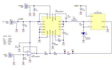
Figure 1 is a synchronous buck converter configured to regulate constant current in the LED.
The op amp (op amp) can be used to adjust the LED current using the control signal (VCNTL). For its part, the controller continuously adjusts the duty cycle and output current to maintain a voltage of 0.8V on the VSENSE pin. If the op amp output voltage rises, it also raises the voltage on VSENSE, so the controller adjusts the LED current down to prevent VSENSE from rising.
Figure 2 is a simplified SPICE model of Figure 1 of a simulated control loop. VC1 is the voltage on the COMP pin that directly drives the power stage with a transconductance gain of 13 (see Figure 31 in the TPS54218 data sheet for more internal details of the controller). This current directly drives the LED through the inductor and the sense resistor. It should be noted that changes in inductance and LED values ​​do not affect the response because the current in the inductor is controlled.
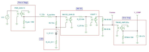
Figure 2. A simplified control loop AC model to measure gain and phase margin.
The shunt monitor transfer function is just a voltage-to-voltage gain of 20 with a high frequency pole (and buffer) close to 500 kHz. This output is provided to the R6/R8 divider. Since the output is a DC voltage, the voltage divider is grounded at the output of op amp U3. The final part of completing this feedback loop is the internal transconductance amplifier of the buck converter, which has a voltage-to-current gain of 225uA/V.
The external compensation component C6 is grounded from this point (V_COMP). It should be noted that V_COMP is also the starting point of our loop simulation (VC1). The loop gain is the measured voltage on the V_COMP pin divided by the injection disturbance on VC1. Therefore, by setting VC1 to the 1 Vac signal, the loop gain is ultimately the voltage measured on V_COMP.
Figure 3 shows the measured responses on the VSENSE and V_COMP nodes. V_COMP stands for loop gain and phase margin, while VSENSE is the power stage, which is the entire loop except the compensation op amp. The most notable point here is that VSENSE, the response up to COMP capacitor C6, is flat. Due to the current mode control, the power stage response is flat and only the shunt monitor response begins to slightly degrade the phase at higher frequencies.
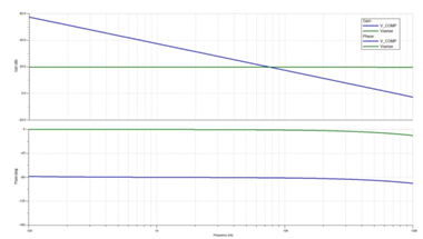
The simulation results in Figure 3 show a very smooth response, at which point the entire loop is primarily set by C6.
The converter loop gain and bandwidth adjustments are individually set by C6. A smaller C6 value will increase the gain due to its higher impedance, while a larger value will reduce the gain. The gain value should be set low enough to ensure good stability and avoid pushing the gain value too high. There are other second-order effects not included in this model, such as slope compensation, which affect gain and phase at higher frequencies.
In addition, this model provides an excellent first-order approximation and an in-depth look at the loop gain of the current-mode synchronous buck LED regulator.
Author: John Betten, Texas Instruments Applications Engineer
Light-resistant design ,and support single and muilt touch points,widely use to financial telecom service,Adverstisement show,Industrial control ,public query ,self-service,E-education ,and games etc aera.Ultra-thin, ultra-narrow design, no matter whether it is external or built-in, it can adapt to various needs without affecting the appearance and saving built-in space. Infrared sensing principle, simple finishing, LED die, stable performance, high touch precision and long life.The unique installation method makes the installation of the client a breeze.The surface of the aluminum alloy is sprayed and oxidized, and the whole is delicate, simple, generous and multi-touch. Simple operation, USB connection, plug and play.
Picture show:


Diy Infrared Touch Frame,Infrared Touch Screen Kit,Install Infrared Touch Frame,Ir Touch Frame Diy,Usb Infrared Touch Screen,Outdoor Infrared Touch Screen
ShenZhen GreenTouch Technology Co.,Ltd , https://www.bbstouch.com