Zhu Hongyu, Li Yu, Fu Xuebin, Xi'an Institute of Electronic Engineering
Keywords: intelligent platform management interface; I2C; VPX
0 Preface
With the continuous improvement of bus bandwidth and real-time transmission requirements in areas such as industrial control, signal processing, and defense, the traditional VME, CPCI, and other parallel bus standards gradually become incompetent, and VPX has emerged as a standard based on high-speed serial bus technology. . In addition to introducing the latest serial bus technology to support higher backplane bandwidth, VPX also introduced Intelligent Platform Management Interface (IPMI) to monitor the system's operational status and provide system reliability. This paper introduces the function of IPMI of intelligent platform management interface in detail, and gives the implementation method of intelligent platform management interface in VPx system.
1 Introduction to Intelligent Platform Management Interface
IPMI (Intelligent Platform Management Interface) is an open standard hardware management interface specification that defines a specific method for the embedded management subsystem to communicate. Users can use IPMI to monitor the physical health characteristics of the server, such as temperature, voltage, fan status, and power status.
Since its inception, Intelligent Platform Management Interface IPMI has been supported by several vendors, which has gradually become a hardware management specification that completely includes servers and other systems (such as storage devices, networks, and communication devices) on the server as well as Telecommunication equipment based on ATCA (Advanced Communication Computer Architecture) has been widely used.
The main components of the IPMI-based intelligent platform management system are shown in Figure 1.
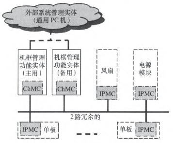
Figure 1 Block diagram of the IPMI Intelligent Platform Management System
a. Distributed Management Controller - manages and monitors the operational status and failure status of each FRU (Field Replaceable Unit) in the system, including ChMC (Frame Manager) and IPMC (Intelligent Platform Management Controller onboard).
b. IPMI other auxiliary functions - provide communication, management and control functions between the distributed control unit and the overall control unit of the system, such as the IPMB (Intelligent Platform Management Bus) interface and the IPMI Ethernet interface.
c. Single-board TCP/IP-based high-level management services such as remote boot, SNMP (Simple Network Management Protocol) management, remote disk services, and Remote Management and Control Protocol (RMCP).
The ChMC is responsible for the power-on/off control of all boards in the system chassis, recording and alarming of temperature and voltage monitoring information, reporting of board running status, and speed control of air-cooled fans.
IPMC is a management controller on the FRU. Its main responsibilities are to manage FRUs (including power-on, reset, voltage and temperature monitoring, etc.) and to collect key events on the FRU.
The data link between the IPMC and the ChMC is two IPMB (I2C) buses, and the redundant dual-bus ping-pong transmission architecture greatly improves the reliability of the data link.
The FRU is the general name of the field replaceable unit. Field replaceable boards, cooling fan trays, etc. can all be called FRUs.
The basic working principle of IPMI is as follows:
IPMI generally uses an independent power supply and is powered on before the system function circuit. After the board IPMC is powered on, it first obtains the location information (slot number) of the board, and then sends the board information to the ChMC through two IPMB buses. Electricity request.
After confirming the board information, the ChMC sends power commands to each board in turn.
After receiving the power-on command, each board IPMC controls the load of the board and powers on. At the same time, it starts monitoring the voltage and temperature of the board and obtains the working status of the board from the CPU through the dedicated serial interface.
When the board voltage, temperature, or working status is abnormal, the IPMC sends an alarm to ChMC. At the same time, in response to the query command of ChMC, the voltage, temperature and working status of the board are reported to ChMC.
ChMC can receive the query request from the host computer monitoring system through the network, and issue inquiry requests such as temperature, voltage, and working status to each board's IPMC, and automatically report the system alarm information to the upper-level monitoring system and record the system working log.
2 Application of IPMI in VPX System
The design of the VPX system also introduces the IPMI intelligent platform management interface. On the P0 terminal, four single-ended signals, SM1–SM4, are reserved for two IPMB buses.
Figure 2 shows the application of IPMI in the VPX system.
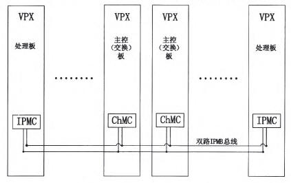
Figure 2 Application Diagram of IPMI in VPX System
Taking into account the importance of ChMC in IPMI, ChMC designs use 1+1 redundant backup mechanisms to improve the reliability of IPMI systems. After the two ChMC units are powered on, their active status is confirmed through the active and standby competition mechanisms. At the same time, heartbeat messages are used to detect each other. When the peers are found to be working abnormally, a hard reset signal is sent to the two ChMC units and an active/standby switchover is performed automatically to ensure that the IPMI system functions properly. jobs.
The ChMC can be physically two independent boards, or it can be an independent circuit on the system's main switch board. (The main switch board also adopts a 1+1 redundancy backup method to improve system reliability. ).
The onboard IPMC is an independent circuit unit on each VPX board and is powered by the backplane 3.3V_AUX.
2.1 IPMB bus design and implementation
The IPMB bus uses I2C communication technology and is defined on the four single-ended signal terminals SM1 to SM4 of the P0 terminal. In view of the inherent characteristics of the I2C bus, although the redundant ping-pong communication method is used, the bus locking phenomenon cannot be avoided. Therefore, the design needs to pay attention to the following aspects:
a. Bus Isolation and Hot Swap
According to the IPMI specification, the IPMB bus is hot-swappable, so the LTC4307 from Linear Corp. was chosen. This chip is a dedicated I2C bi-directional isolated buffer that provides a rise-time accelerator to reduce the bus rise time due to overload, 1V preload. Charge voltage to reduce bus interference, also has the bus lock automatic detection and recovery.
b. Bus Drive Capability Calculation
The maximum capacitive load capacity of the I2C signal is 400pF, so the load capacity of the IPMB must be properly designed. Select a suitable pull-up resistor based on the capacitive load to ensure the bus's drive capability.
For a board, the capacitive load includes the following parts:
· Connector capacitive load to backplane: 2pF
· Connector PCB Through Hole Capacitive Load: 1pF
· Lead and Via Capacitive Loads: 9pF
·I2C driver: 10pF
In addition, the capacitive load of the backplane traces also needs to be taken into account.
Pull the IPMB bus to the 3.3V_AUX power supply through the calculated pull-up resistor on the backplane. The insertion and removal of the board will not affect the bus's drive capability.
c. Bus lock anticipation and processing
The locking of the I2C bus can be divided into two kinds according to the reasons, that is, the slave device does not respond and the bus locks or the master device fails to cause the bus to lock.
Each LMC4307 isolation buffer is designed on the hardware of the node board that connects to the IPMB bus. When the device detects that the SCL or SDA signal line remains low for more than 30ms, it automatically disconnects the node board from the bus. Sends 16 SCL clocks and a stop signal to the board side to return the bus to its normal state.
In software, corresponding monitoring and pre-judgment mechanisms should also be designed to ensure the stable operation of the IPMB bus.
Once the IPMC unit detects that the heartbeat message cannot be obtained from the IPMB bus, it immediately controls the LTC4307 to disconnect the local board from the IPMB bus, records the fault alarm information, resets the I2C controller, and reopens the LTC4307 to try to communicate with the ChMC. Still fail, disconnect the board from the bus, and light the alarm indicator to prompt manual intervention.
The ChMC unit monitors heartbeat messages (including redundant ChMCs) of all the cards. When detecting that the IPMB heartbeat message of a board card is lost and the heartbeat messages of other card cards are normal, the card is pulled out or faulty. Record and Upload alarm information. When all heartbeat information is detected, confirm that the board is faulty, immediately control the LTC4307 to disconnect the board from the IPMB bus, record the fault alarm information, and then reset the I2C controller, and re-clock the LTC4307 to try to communicate with other boards. Still fail, disconnect the board from the bus, and light the alarm indicator to prompt manual intervention.
2.2 Chassis Management Unit ChMC Design
The IPMI design should be based on the following principles:
a. Low power consumption - 3.3V_AUX power consumption of VPX system provided to each slot IPMI module is less than 1A;
b. hardware integration design - saves the circuit area for some functions of the system to save the PCB area, while low complexity hardware design reduces the risk of hardware failure;
c. The software design is simplified to reduce the risk of software failures and ensure that IPMI software has high reliability;
Based on the above principles, the ChMC hardware circuit should meet the following requirements:
a. With two I2C interfaces connected to two backplane IPMB buses.
b. It has 2 UART (Universal Asynchronous Serial Interface) interfaces, 1 channel is used to communicate with the functional unit CPU to obtain the board running status information, and 1 channel is used as the debugging interface.
c. With multi-channel ADC module for monitoring the power supply of the functional circuit.
d. A LAN (Ethernet) communication interface is used to connect a remote PC to receive control from a host system management system.
e. With abundant GPIO resources, it is used to control functions such as power-on and power-off of the functional circuit, reset, acquisition of slot information, and temperature monitoring of the board.
f. Have a watchdog circuit to increase the reliability of the system software.
TI's ARM Cortex-M3 processor LM3S6918, single chip can meet the above functions, the processor operating speed up to 50M, integrated RTC, watchdog function, external interface is very rich, with 2 I2C interface, 2 UART interface, integrated 10/100 Ethernet MAC and PHY, up to 38 GPIO, integrated 8-channel 12-bit ADC, typical power consumption is only 100 mA.
The concrete implementation block diagram of ChMC is shown in Figure 3.
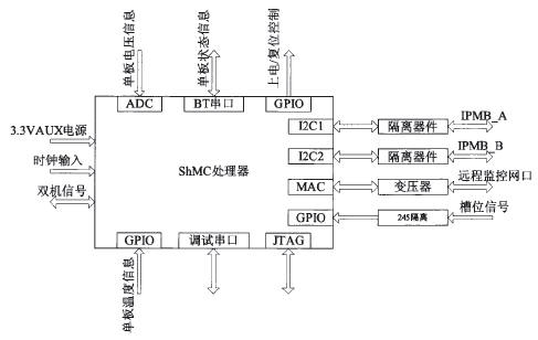
Figure 3 Block diagram of the chassis management unit chMc
Because ChMC is responsible for managing the entire chassis, ChMC should be one of the most reliable components in the entire system. In addition to the emphasis on its reliability design in software and hardware design, most designs use a master-standby redundancy design scheme to further improve the unit's reliability. The competitive circuit is the key in the active and standby redundant design. The following gives a method for implementing the main and standby competition circuits of the ChMC (see Figure 4).
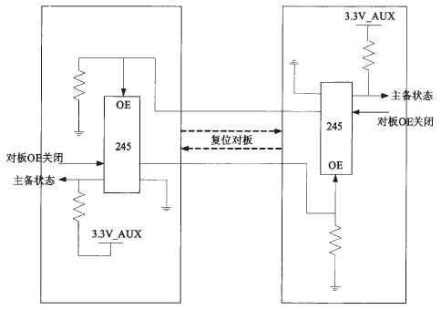
Figure 4 ChMC active and standby competition circuits
The specific working principle is as follows:
After the ChMC is powered on, it first obtains the slot number, and then sends a signal to the board OE to shut down. Then, the active and standby status information of the board is obtained.
When two boards are successively powered on (inserted into the chassis), the 245 enable signal OE on the power-on board is turned off by the power-up board. At the same time, the board's OE turn-off signal is sent to the board 245. Because the board is isolated, the status of the active/standby board read is "1", that is, the standby state. The board 245 that is powered on first is enabled by default. The active/standby status read is "0", that is, the active status.
When two boards are in the chassis and are powered on at the same time, the system design defaults to use the ChMC as a main slot. When the software is designed, the delay will be different depending on the slot number. The standby chMc delays for several microseconds when sending a signal to the board OE to ensure that the main ChMC works first.
When the IPMI works normally, the active and standby ChMCs periodically send heartbeat messages to each other and monitor the heartbeat messages sent by each board's IPMC. When the standby ChMC discovers that the active ChMC heartbeat message cannot be received, it can monitor the IPMC heartbeat messages. It can confirm that the main ChMC is faulty, send the master ChMC reset signal, and reset it. After the master ChMC reset, it will release the OE close signal of the board, meanwhile it will receive the OE shutdown signal sent by the standby ChMC, and the standby ChMC will train to the master and slave state. When it becomes "0", it switches to the active state, and the original master ChMC detects that the master/backup state indicator has changed to "1" and switches the board to the standby state accordingly.
In the ChMC reset process, the IMB isolation device automatically isolates itself from the IPMB bus. After the reset is completed, the IPMB bus is accessed.
The primary and secondary contention signals are implemented on user-defined single-ended signals in the VPX connector.
2.3 Onboard IPMC Design
The biggest difference between onboard IPMC and ChMC above is the design of IPMI management software. The hardware design of the two are basically similar. For details, see the ChMC unit.
In addition to monitoring the voltage and temperature information of the board, the onboard IPMc must also obtain the operating status of the functional circuit of the board and report the failure alarm information of the functional circuit to the ChMC. The monitoring of the functional circuit status is generally performed by the CPU of the local board, and the monitoring information is reported to the IPMC through a dedicated serial serial port. This function is also implemented when ChMC is integrated as a hardware unit on a function board. From the perspective of reliability and cost, most designs are based on the IPMI specification to simplify the design, so IPMC does not consider the implementation of Ethernet communication in design, and there is no main and redundant design.
3 Conclusion
This article aims at the specific application of VPX system management, introduces some basic functions of IPMI, and focuses on the description of the implementation of IPMI in VPX system. The solution is based on low-power ARM processor, which can be used as the design of ChMC circuit. For the design of onboard IPMC, only need to make corresponding changes in the software, in addition also introduced the concept of ChMC 1+1 redundancy design, with good flexibility and high reliability.
Tv Speaker,Wireless Soundbar,Single Soundbar Speaker,Soundbar With Wireless Subwoofer
Newmax Electronics Co.,LTD , https://www.fspeaker.com