Design of Wireless Display System Based on Bluetooth Technology
introduction
Bluetooth technology is a short-range wireless communication technology used to replace wired cables. It is a wireless communication technology standard formulated by the SIG organization initiated by multiple companies. The purpose is to replace the existing wired interfaces on devices such as PCs, printers, fax machines, mobile phones and home gateways, to provide voice data and ordinary data for individuals. Wireless transmission. The working frequency band of the Bluetooth device is the 2.4 GHz ISM band that can be used freely in the world; low cost, low power consumption, small size, short communication distance, high security, capable of transmitting ordinary data and voice data Make up piconet and scatter net etc. It has been widely used in many devices such as mobile phones, PDAs, wireless headsets, notebook computers and so on. The ISM band is a frequency band that is open to all radio systems, so using one of these bands will encounter unpredictable sources of interference. For example, some home appliances, cordless phones, car door openers, microwave ovens, etc., may be interference. To this end, Bluetooth technology has also specially designed a quick confirmation and frequency hopping scheme to ensure a stable link.
This article introduces a design scheme of Bluetooth wireless display system. Using Bluetooth technology, the display terminal can be wirelessly controlled in a short distance, and the wireless transmission and display of image and character data can be realized, eliminating the defects caused by the wired connection, and can be applied in various fields.
1 Overall system design
The wireless graphic display system is mainly composed of two parts: the host part and the display terminal part. The host is responsible for the transmission of control commands and data to be displayed, and the display terminal is responsible for receiving and displaying. The system structure is shown in Figure 1. 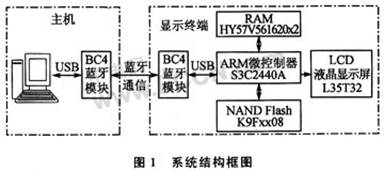
The host part consists of a PC with Linux operating system and the BlueCore4 Bluetooth module connected through a USB interface.
The display terminal consists of an embedded Linux platform with an ARM9 microcontroller S3C2440A as the core, a BlueCore4 Bluetooth module, and an LCD liquid crystal display. The Linux operating system is installed in NAND Flash and connected with 64 MB of external expansion RAM. Because the S3C2440A interface is relatively rich, the system hardware has better expansion performance.
The system communicates through the RFCOMM protocol layer of the Bluetooth protocol stack. The RFCOMM protocol provides serial data transmission and can maintain up to 60 connections between two Bluetooth devices at the same time. It can also support the OBEX protocol in legacy serial port applications and other applications. The block diagram of the Bluetooth protocol stack is shown in Figure 2. 
The working process of the system is: After the system is initialized, the host and the display terminal establish a Bluetooth connection. After the connection is successful, the host application sends a display command to the display terminal through the Bluetooth module. The display terminal performs operations such as receiving image data or character data according to the corresponding command, and then sends the data to the LCD liquid crystal display through the LCD controller. After the system is successfully connected, the display terminal can display different images and character data in real time according to the received data, until the host sends the exit command to end the communication.
2 System hardware design
Both the host and the display terminal use the Bluetooth wireless transceiver module composed of CSR's BlueCore4-ROM chip. The BlueCore4 series conforms to the Bluetooth version 2.0 standard and is fully compatible with existing Bluetooth devices version 1.1 and 1.2. The BlueCore4-ROM chip used here has a high degree of integration and requires very few peripheral parts. It provides host interfaces such as UART, USB2.0, and provides PCM audio interface and SPI interface. It has the advantages of supporting piconet and scattering network, low power consumption, good compatibility with mobile phones, and coexistence with 802.11 protocol. BlueCore4 Bluetooth module structure is shown in Figure 3. 
The PC host uses a USB interface to connect with the BlueCore4 Bluetooth module. The corresponding Bluetooth module is also connected to the USB-HOST interface of the S3C2440A through the USB interface. The USB interface has the advantage of plug and play. With the support of the Linux operating system, the module can also be replaced with a universal USB Bluetooth adapter. The reference circuit principle of the BlueCore4 Bluetooth module is shown in Figure 4. 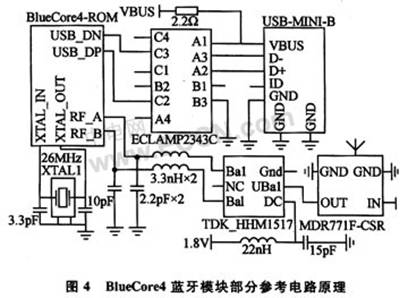
The LCD screen and the S3C2440A microcontroller are connected via the built-in LCD controller interface of the S3C2440A. The LCD screen uses the 3.5-inch L35T32 here. The LCD screen displays 240 × 320 pixels, can display 16-bit color, and can be easily expanded to a larger LCD screen. The reference circuit principle of S3C2440A's USB-HOST interface and LCD controller interface is shown in Figure 5. The LCD controller interface wiring mainly includes: VD0 to VD23 (R, G, B three-color separation information), VCLK (data transmission clock), HSYNC (line synchronization signal), VSYNC (field synchronization signal), VDEN (data enable Yes), LCD_PWREN (display enable).
3 System software design
The system software is also divided into a host part and a display terminal part. Here mainly analyzes the design of the software of the display terminal, and the host part is similar to it. The display terminal part of the program includes: LCD liquid crystal screen initialization, Bluetooth device initialization, Bluetooth connection establishment and image character data transmission display and other parts. The program flow is shown in Figure 6. 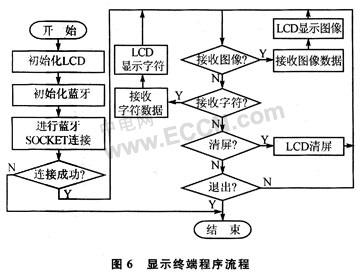
The user program is developed based on the Bluez Bluetooth protocol stack on the Linux operating system. The host application program is compiled using the GCC compiler, and the display terminal application program is cross-compiled using the arm-linux-gcc compiler.
3.1 Bluetooth partial programming
This part adopts Bluetooth socket programming. Connect by establishing a socket of the Bluetooth RFCOMM protocol layer. After the connection is established, you can call the function recv or read to read the data sent by the host, and the host uses the function send or write to send the data accordingly. After the communication is over, you can call the function close to end the connection.
Both the host and the display terminal Bluetooth module have fixed Bluetooth addresses, and the host directly connects to the display terminal device with a fixed Bluetooth address. One host can communicate with multiple display terminals and display images and characters on different display terminals.
The reference procedure of the Bluetooth initialization part is as follows: 
3.2 Partial programming of LCD screen
Some programs of the LCD screen use the framebuffer programming interface of the Linux kernel driver. Framebuffer provides an abstract process for image hardware devices, allowing applications to access image hardware devices through a well-defined interface. The software does not need to know anything about the underlying driver of the hardware. Through the framebuffer, the application can use the mmap function to map the video memory to the virtual address space of the application, and write the data to be displayed in the memory space to display it on the screen. The reference procedures for the LCD display initialization and clearing are as follows: 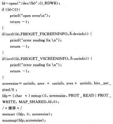
After the initial connection of the LCD screen and the Bluetooth socket is completed, you can send images and character data via Bluetooth. The procedures for receiving and displaying images and characters in Bluetooth are similar. Both read the commands sent by the host by calling the function recv or read. After the program judges, the data is received in the same way. The reference program for receiving and displaying character data is as follows: 
This program uses the received character data to get the corresponding display font data, and then displays it on the LCD screen through the frambuffer display interface. The source program comes with a display font file, which is compiled and embedded into executable code, and then downloaded to the display terminal file system. The system only adds English fonts and corresponding display codes here, which can display English characters normally. If needed, Chinese characters can be easily displayed by adding a Chinese character library and a small number of display codes. The image part program directly displays the received bitmap data on the LCD screen through the frambuffer display interface.
In order to use the Bluetooth protocol stack on the Linux operating system of the display terminal, it is necessary to select the required Bluetooth support option when cross-compiling the embedded Linux kernel, and compile and install the required Bluez Bluetooth library into the terminal file system. The user application program is also cross-compiled to obtain executable code, and then downloaded to the terminal file system to run.
The system can be applied to public information display screens, such as lobby advertising information screens, building prompt signs, etc., to avoid the defects of wired connections. After expansion, the system can also exchange data with mobile phones, PDAs, wireless headsets, and wireless speakers.
4 Conclusion
Bluetooth development is carried out on the embedded Linux operating system through the existing Bluetooth protocol stack, and data is sent and received wirelessly through the Bluetooth protocol layer without concern for the realization of the Bluetooth underlying driver. Users can carry out more complex communications through various upper-layer protocols, and can also send audio data through the Bluetooth SCO protocol layer. Therefore, the development of Bluetooth wireless display system on the embedded Linux operating system platform is more convenient, and has the advantages of good expansion performance.
EO2 is an Ethernet extender over UTP cable. One EO2 at the network end can support one or multi remote models and their connected IP network devices. This EO2 can transmit over telephone line, Ethernet cable, and twisted pair. It is provided with excellent lightning protection and anti-interference capacity. In the real work environment, the network bandwidth could reach up to 60Mbps. With the Ethernet extended to 750meter, it has enlarged the Ethernet network application area, cutting down the project cost by using Cat5e or Cat6 cable.
N-net EO2 series have POE function, powering remote EO2 transceivers and their connected IP network device, default as a master terminal.
Ethernet And Power Over UTP Cable Converter
Ethernet And Power Over UTP Cable Converter,Power Over Ethernet,UTP Cable Converter,POE over UTP Cable Extender
Shenzhen N-net High-Tech Co.,Ltd , http://www.nnetswitch.com