[Photo] Simple FM FM transmission experiment


Simple FM FM transmission experiment
At present, the launch experiment suitable for making by yourself is the FM equipment such as wireless microphones. Although there are many such articles in various newspapers and periodicals, the newspapers and periodicals lack interactive means. It is very inconvenient for fans to encounter problems during the production process. Readers communicate. In addition, the production articles selected by the editorial department of the newspapers and magazines may not always be verified. Therefore, some authors conceived the production to bring difficulties to beginners.

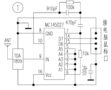
This is a relatively simple and practical production. This article intends to go from simple to complex step by step. If you are willing to experiment with synchronization, you will soon be able to make an FM transmitter suitable for formal occasions. Of course, the experiment starts from the simplest. The following figure is a simplest oscillator, which is the basis of FM transmission.

The coil in the picture is wrapped with a 1.0mm enameled wire on a 3.2mm drill bit for 6-8 turns, which can cover 88-108MHz, and 7 turns around 100MHz. Connect it as shown in the picture above. In fact, it is already a simple transmitter. It can transmit when powered on. However, it transmits an unmodulated constant-amplitude signal. When the nearby FM radio receives the signal, it will only be silent. Add the modulation signal as shown in the figure below, and you can enter the practical state.

At this time, if you connect the audio source signal output from the Walkman, DVD player, etc. to the audio input terminal of the transmitter above, you can listen to it with a radio nearby. Although the above picture can be launched, it is not practical. The first is that the transmitted energy is very small and can only be used indoors. It is only a few tens of meters outdoors. The second is the frequency instability. Since the antenna is just a piece of wire, it is connected to the oscillation circuit through a 100P capacitor, so the environment around the antenna will affect the transmission frequency. If you want to make it usable, you should add two poles to enlarge it, see the figure below.

This is a power amplifier circuit built at the request of netizens. The output power is satisfactory, but there are many problems, which will be described in detail below. The oscillator and the power amplifier are connected together to become a complete FM transmitter, see the figure below.

The transmitter in the picture is easy to make successfully. The success mentioned here is that you can plug in the antenna and turn on the power to enter the working state. If you want the transmitter to enter the best working state, you need to do some debugging. In fact, the biggest fun for enthusiasts to do experiments is to make the works more perfect and get the best performance through hands-on debugging.

First of all, this output circuit works in a non-class A state, which has stricter requirements on the load impedance. Usually the transmitter is mostly 50Ω output. It is not easy to find 50Ω RF cables for enthusiast experiments, and 75Ω RF cables can be everywhere. You can buy it, and the 75Ω antenna is also easy to make, so this machine uses a 75Ω output. Before powering on, you should connect a 75Ω resistor to the output. After debugging, connect the 75Ω antenna. The maximum output of this machine is more than 1W, don't use that kind of small resistance of 1 / 8W, connect it and burn. It's fine to burn a resistor, but when the resistor is burned, the amplifier is equivalent to no load, and the tube is dangerous.

The main content that needs to be debugged after power-on is the working point of the launch tube, and the harmonic components of different outputs at the working point are greatly different. The operating point of the transistor selected by the oscillating stage of this machine makes it more dynamic. The measured second harmonic is more than 20 decibels lower than the fundamental wave, and the third and fourth times are lower, which is completely negligible. The driving level works in the state of Class A and Class B, which is close to Class A, and does not generate harmonics of large energy. The key is in the output stage. The selection of the working point of the output stage is more troublesome. The partial voltage formed by the upper bias resistor and the lower bias 51 Ω resistor should be lower than the launch junction voltage of the launch tube, making it work between Class B and Class C states. When 1KΩ is selected, it is close to Class B. At this time, the working current of the launch tube is 260mA, the output power is 700mW, the second harmonic is about 10dB lower than the main wave, the third and fourth times are lower, and the output frequency energy is above 500mW.

With the increase of the upper bias resistance, the working state of the launch tube will be close to Class C. The indicator of the power meter will gradually increase, up to 1300mW at the maximum, but each harmonic at this time also gradually strengthens, and the main wave power instead reduce. In professional manufacturing, this contradiction is not difficult to solve, but this circuit is a simple type designed for beginners, so it has to give up the power efficiency index, and it is recommended to use 1KΩ for the upper bias resistor. During the experiment, 2SC2053 was severely heated. Although it was not damaged during the experiment, it is estimated that it will not work for a long time. It is recommended to use 2SC1970 or use two 2SC2053 in parallel during production. Pay attention to the current sharing measures when connecting in parallel. If you just want to taste the fun of hands-on production, you do not necessarily need such a large output power, nor do you need to transmit far, then you can make some changes to the circuit parameters, the circuit structure remains unchanged, with 6V power supply, the output power is also Above 100mW, see the figure below.

The circuit structure is exactly the same as the above figure, except that the values ​​of several components have been changed, and the transistors have also been adjusted. Due to the small output power, the use of 3355 for output does not need to consider the safety of the output tube, and can work stably for a long time.

In-depth analysis of the first-level cache and second-level cache of the technical zone CPU eMMC mass burning dilemma, do you really know? Isolation flyback and non-isolated BUCK application design plan Schottky barrier diode selection and application guide How to use Altium in program design Designer puzzle?

Follow WeChat

Interesting and informative information and technical dry goods

Download Audiophile APP

Create your own personal electronic circle

Follow the audiophile class

Lock the latest course activities and technical live broadcast
Collect People collection
share it:
comment
Publish

related suggestion

[Photo] Simple voltage regulator circuit

Alternating current can be converted into direct current through rectification, but its voltage is unstable ...

Posted at 2006-04-16 22:42 • 877 views
[Photo] Simple voltage regulator circuit
Simple and practical mouse remote control device

The device uses the coding and decoding circuit MC14526 / MC14502 and the RF transmission / reception module TDA1808 / TDA ...

Posted at 2006-04-16 17:29 • 244 times read
Simple and practical mouse remote control device
[Photo] The ordinary Huawei 3G mobile phone U636 in detail ...

Although the production on the mobile phone terminal does not temporarily have a large scale, but for the name of Huawei, ...

Published on 2006-04-15 22:38 • 293 views
[Photo] Uncommon in the simple Huawei 3G mobile phone U636 in detail ...
var check_allow = "/d/Api/iscantalk.html"; var add_url = '/ d / article / write /'; function CheckLogin () {now_uid = ''; var ElecfansApi_checklogin = '/ webapi / passport / checklogin'; var logout_url = "{: U ('Login / logout')}"; var logout_url = 'http://bbs.elecfans.com/member.php?mod=logging&action=logout&refer=front'; $ .get (ElecfansApi_checklogin, function (data, textStatus) {if (data! = "") {EchoLoginInfo (data); CheckEmailInfo (data); data = $ .parseJSON (data); now_uid = data.uid; / * var login_content = 'write an article
'+ data.username +'
Quit '; * / var login_content =' write an article
'+ data.username +'
Set exit '; $ (' # login_area '). Html (login_content); var win_width = $ (window) .width (); if (win_width> 1000) {$ ("# mine"). MouseDelay (200) .hover (function () {$ ("# mymenu"). show ();}, function () {$ ("# mymenu"). hide ();});}} else {var content = 'Login Registration'; $ ('# login_area'). html (content); $ (". special-login"). click (function (e) {$ .tActivityLogin (); return false;});}});} $ (function () {// comment ------------------------------- var comment = $ ("# comment"); var comment_input = $ ("# comContent"); // Submit comment click event interaction $ ("# comSubmit2"). on ('click', function () {var content = comment_input.text (); // Empty input box comment_input. html (""). focus (); // Submit data to server $ .ajax ({url: '/plus/arcComment.php', data: {aid: $ ("# webID"). val (), dopost : 'apiPubComment', content: content}, type: 'post', dataType: 'json', success: function (data) {// Data format returned: if (data.status == "successed") {// Build temporary comment DOM var dom = ''; dom + = '
'; dom + =' '; dom + ='
'; dom + ='

'+ data.data.username +' '; dom + ='

'; dom + =' '+ content +' '; dom + =' '; dom + =' just now '; dom + =' '; dom + =' '; // insert a temporary comment to the list $ ("# comment ") .append (dom);} if (data.status ==" failed ") {// alert (data.msg); layer.msg (data.msg);}}}); return false;}); (function () {/ * * Insert single sign-on JS * / var setHost = 'https://passport.elecfans.com'; // Set domain name var script = document.createElement ('script'); script.type = 'text / javascript'; script.src = setHost + '/public/pc/js/t.passport.js'; script.setAttribute ("id", "sso_script"); script.setAttribute ("data-ssoSite", setHost); script.setAttribute ("data-ssoReferer", encodeURIComponent (location.href)); script.setAttribute ("data-ssoSiteid", "11"); var body = document.getElementsByTagName ("body"). item ( 0); body.appendChild (script);}) () / * * It is recommended to modify the style of the article without a picture * * / $ (". Article .thumb"). Each (function () {if ($ (this). find ('img'). attr ('src') == "") {$ (this) .find ('img'). remove (); $ (this) .parent (). css ('padding-left ',' 0px ');}}); / * Baidu share * / window._bd_share_config = {common: {bdText: '', // Custom share content bdDesc: '', // Custom share summary bdUrl: window.location.href, // Custom share URL address bdPic: ''} , share: [{"bdSize": 60, "bdCustomStyle": true}]} with (document) 0 [(getElementsByTagName ('head') [0] || body) .appendChild (createElement ('script')). src = 'http://bdimg.share.baidu.com/static/api/js/share.js?cdnversion=' + ~ (-new Date () / 36e5)]; var add_url = '/ d / article / write / '; // var check_allow = "{: U (' Api / iscantalk ')}"; var check_allow = "/ d / api / iscantalk"; var click_items_length = $ ('. art_click_count '). length; if ( click_items_length> 0) {var id_str = ''; $ ('. art_click_count'). each (function () {id_str + = $ (this) .attr ('data-id') + ',';}) // var url = "{: U ('Api / getclickbyids')}"; var url = "/ d / api / getclickbyids"; var id_data = 'id_str =' + id_str; $ .ajax ({url: url, data: id_data, type: 'post', dataType: 'json', success: function (re) {if (re.list.length> = 1) {var list = re.list; for (var i in list) {var t emp_id = list [i] ['id']; var temp_span = $ (". art_click_count [data-id =" + temp_id + "]") temp_span.html (list [i] ['click']);}} }})} $ ("# comContent"). click (function () {if (now_uid == '') {$ .tActivityLogin (); return false;}}) $ (function () {var follow_wrap = $ ( ".author-collect"); var now_uid = "{$ _super ['uid']}"; var face_src = "{$ _super ['uface']}"; var getFollowNum = $ (". followNum strong"). html (); // Follow $ (window) .on ('click', '.author-collect', function () {if (now_uid == '') {$ .tActivityLogin (); return false;} if ( $ (this) .attr ('id') == 'follow') {$ .post ('/ d / user / follow', {tuid: article_user_id}, function (data) {// Data format returned: if (data.status == "successed") {$ (". followNum strong"). html (++ getFollowNum); follow_wrap.html ('followed'). attr ('id', 'cancelFollow'). css ( 'background', '# 999'); var follow_user = ' '; $ (' # follow_list '). append (follow_user);} if (data.status == "failed") {alert (data.msg);}});} else {// Unfollow if ($ ( this) .attr ('id') == 'cancelFollow') {$ .post ('/ d / user / cancelFollow', {tuid: article_user_id}, function (data) {// Data format returned: if (data .status == "successed") {follow_wrap.html ('Follow'). attr ('id', 'follow'). css ('background', '# f90'); $ (". followNum strong"). html (-getFollowNum); $ ('# follow_list .face'). each (function () {var target_uid = $ (this) .attr ('data-uid'); if (target_uid == now_uid) {$ ( this) .remove ();}})} if (data.status == "failed") {alert (data.msg);}}); return false;}}});});}); / * var myface = "{$ _super ['uid'] | avatar}"; var myname = "{$ _super ['username']}"; var article_id = {$ article ['id']}; var article_user_id = {$ article ['mid']}; // Article author ID $ (function () {<notempty name = "clearnum"> // Reduce the number of reminders var count = parseInt ($ ("# noticeCount"). html ()); count = count-{$ clearnum}; $ ("# noticeCount"). html (count); if ( count

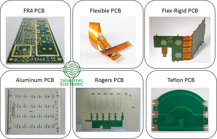
Flex-Rigid PCB, it's the PCB that part of it is rigid and part of it is flex. It combine flex PCB and rigid PCB in a same PCB together and we call it flex-rigid PCB or rigid-flex PCB. Normally, the rigid PCB area is for soldering electronic components and the flex PCB area would be taken as cables to connect rigid PCB areas together, this could make the rigid-flex PCB perfectly suit for a wide range of applications.


PCB = printed circuit board and PCBA = printed circuit board assembly. For PCB, it means the copper circuits be printed on a board, and so the main composition of PCB are copper and board.


The copper is the circuits material and the circuits designed by the PCB designers. Depends on the current in the circuits, the PCB copper thickness could be done with 0.5oz-10oz. But the PCB designers need be noted that the copper track width/space need be enlarged with the thickness. For example, the minimum copper track width/space could be 3mil/3mil with 0.5oz, but would be 4mil/4mil with 1oz.


The PCB board could be rigid PCB, could be flex PCB and also could be flex-rigid PCB. And the materials could be FR4, PI, Aluminum, Copper-based, Rogers, Teflon, etc. They have different applications. For example, FR4 PCB is the most commonly used for rigid PCB and almost good for all electronics products; PI is the most commonly used for flex PCB; Aluminum and copper-based have good thermal diffusivity and always used for LED PCB ; Rogers PCB and Teflon PCB are always used for High Frequency PCB, etc.


We are the one-stop shop for all kinds of PCB manufacture service from PCB Prototype to big volume, which could save our customers a lot of time and money.


PCB Manufacture Capabilities


Features 

 Capabilities

Layers

1-36 layers

Material

 FR-4, Aluminum, Copper, Polyimide, high frequency (Rogers, PTEE, PI), etc.

PCB Type

FR-4 Standard PCB , Aluminum PCB , Copper-based PCB, HDI PCB , Rigid-Flex PCB, Flex PCB, Thick Copper PCB and Rogers PCB, etc.

Board Thickness

0.1mm-6.0mm

Copper Thickness

1/2oz-6oz(18um-210um)

Biggest Board size

600mm*1200mm

Min Tracing/Spacing

0.075mm/0.075mm (3mil/3mil)

Min drilling Hole diameter

0.15mm(6mil), 0.1mm(4mil)-laser drill

Solder Mask

Green, Black, White, Red, Yellow, Blue and Purple, etc.

Silkscreen color

White, Blue, Black, Red, Yellow

Surface finish

HASL Lead free, Immersion Gold (ENIG), Immersion Tin, Immersion Silver, OSP, Carbon oil, etc.

Special Techniques

Impedance Control, Gold Fingers, Blind/Buried vias, Peelable solder mask, Half holes, Via-in-Pad and Countersink hole, etc.


PCB Products Show


PCB Boards_1


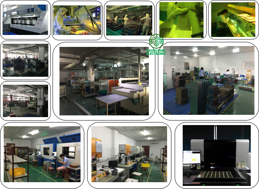
PCB Factory Show


Yifang PCB Factory

Flex-Rigid PCB

Flex-Rigid PCB,Multilayer Rigid-Flex PCB,Rigid Flex PCB,Rigid Flex PCB Board

ZhongFeng Electronic Technology Co., Limited , https://www.dopcba.com

Posted on