Use antenna diversity to create a robust radio communication link
Initially, many designers may worry about the complexity of regional specifications, because the specifications are different in different regions of the world. However, as long as more research is done, it will be possible to understand and comply with the regulations of different regions, because in each region, there is usually a government unit responsible for promulgating relevant documents to explain the relevant regulations of the transmitter that meets the specific purpose.
The more difficult part to understand in radio communication is that the quality of the radio communication link is related to a variety of external factors. A variety of variable factors are intertwined to create a complex transmission environment, which is often difficult to explain clearly. However, mastering basic concepts often helps to understand the changing quality of radio communication links. Once these basic concepts are understood, many of the problems can be solved by a low-cost, easy-to-implement technology called antenna diversity. achieve.
Environmental considerations
The primary environmental factors affecting the continued stability of radio communication links are phenomena called multipath / fading and antenna polarization / diversity. The impact of these phenomena on link quality is either constructive or destructive, depending on the specific environment. There may be too many things happening, so when we try to understand the effect of certain environmental conditions on the radio communication link at a certain point in time, and what kind of link quality will be caused, this is undoubtedly very difficult.
Antenna polarization / diversity
This phenomenon, called antenna polarization, is caused by the directional properties of a given antenna. Although antenna polarization is sometimes interpreted as attenuation in the quality of certain radio communication links, some radio communication designers often use this One characteristic is to adjust the antenna, by limiting the transmission and reception signals to meet their needs within a limited range of directions. This is feasible because the radiation of the antenna is uneven in all directions, and this feature can be used to shield RF noise from other sources.
Simply put, antennas are divided into omnidirectional and directional. When the omnidirectional antenna transmits and receives signals, the strength in all directions is the same, while the directional antenna's transmit and receive signals are limited to one direction. If you want to build a highly solid link, you must start by understanding this application. For example: if the signal on a link only comes from a specific direction, then choosing a directional antenna will benefit more. A receiver equipped with a directional antenna receives signals from transmitters that are within the line-of-sight direction range determined by the antenna's directional properties, while signals from other transmitters that are outside the direction range are shielded.
A transmitter equipped with a directional antenna emits most of its energy in a predetermined direction, instead of transmitting in all directions, and does not reduce its coverage.
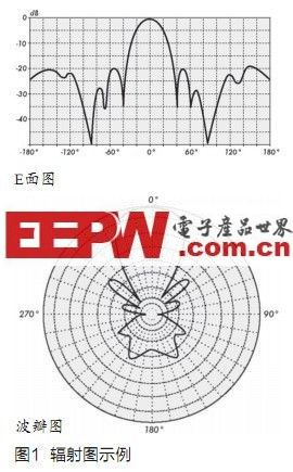
In order to simplify the understanding of the antenna profile, antenna manufacturers provide antenna radiation patterns. Antenna radiation patterns have different formats, such as E plane plot and polar plot, as shown in Figure 1. In addition to the directionality or shape, the E-plane diagram provides a lot of information, but it is usually not as clear as the lobe diagram says. The lobe pattern is designed to resemble a compass, making antenna gain in any given direction easier to understand.
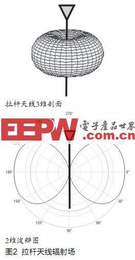
In Figure 2, the engineer can see an advanced two-dimensional view indicating how the antenna is operating on the predetermined plane. However, the antenna also tends to change the characteristics on other axes, but usually does not provide three-dimensional graphical data, because this will significantly increase the complexity of the chart. The whip antenna is a typical omnidirectional antenna, which has a simple three-dimensional profile. In plan view, whip antennas can provide excellent coverage, but in three-dimensional graphics, they perform very poorly directly above or below themselves, which helps us to better understand the antenna is placed in a two-story indoor environment Case.
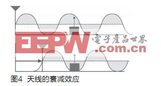
Generally, because the RF signal is reflected by walls and other indoor objects, it is difficult to observe the effect of antenna polarization. However, other effects that may be constructive or destructive to the RF signal can still be observed. Path / Attenuation. This kind of attenuation is usually observed when the transmitter or receiver moves slightly and makes a huge difference in link quality. This happens when the antenna is receiving and transmitting signal peaks.

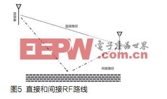
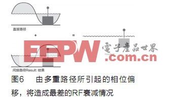
Multipath is an extension of this concept. When radio communication waves are transmitted, they may be received by more than one path by the receiver. Due to the reflection of other objects (such as walls and trees) forming multiple paths, signals may come from multiple paths. When receiving signals from these sources, the time of arrival may be slightly different, which means that a slight phase shift may occur. When these signals are combined, they may cause the disappearing form of "attenuation". One of the worst cases is that the two signals arrive at the receiver with a phase difference of 180o. The receiver will not be able to see any data, causing 100% signal attenuation. In most cases, the receiver is unlikely to receive two signals with a phase shift of 180o, but when a multipath environment occurs, some phase shift may still occur. In these cases, Some signal attenuation will occur.
Antenna diversity
Antenna diversity is a technique used to restore signal integrity. The antenna that achieves antenna diversity in the product has a 90 ° antenna frame with another antenna, so the effect of polarization / directionality will not reduce the quality of the potential radio communication link. In addition, the position of the antenna frame of each antenna in the product that realizes antenna diversity will maintain a distance of at least 1/4 wavelength, so as to ensure that at least one antenna is in the peak of the waveform.
Although antenna diversity is beneficial for restoring signal integrity and maintaining link boundaries from environmental influences, it must be sacrificed in other ways, which means that the overall cost of the microcontroller (MCU) increases because of the micro-control The transmitter must be on standby for a long time to evaluate the antenna signal at all times. The increased functionality of the microcontroller will lead to the need for a higher specification and more expensive microcontroller, and the microcontroller must "stand by" at any time, also resulting in shortened battery life. In other cases, the solution using two antennas will add additional space requirements or require other coding expertise, which limits designers to a single antenna design.
Coding an antenna diversity system will increase the coding burden on the design. Many antenna diversity systems are optimized to operate in a synchronized manner. The microcontroller on the receiver has a timing function to let the receiver know when to start receiving data. In these cases, the microcontroller can immediately start evaluating the signals of the two antennas. To evaluate this signal, the microcontroller switches each antenna and evaluates the Received Signal Strength IndicaTIon (RSSI) level. In other products where the receiver does not use a timer, radio communication must detect the beginning of a packet because the preamble signal may be misinterpreted as noise (or vice versa). Unfortunately, the strong Noise may cause the start of packing to be missed.
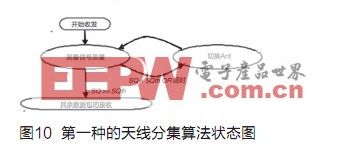
To confirm that the frequency of this antenna switching is sufficient to capture the packing of one of the antennas, whenever this algorithm enters the "Measure SQ" function, a timer is started.
Minimum switching time
Among them: TPL is the longest time that can be used to select the antenna in a specific signal part (such as a packed preamble signal) N is the number of antennas used by the diversity receiver.
During the operation of the "Measure SQ" function, the signal quality (SQ) will be measured. If the SQ is below the signal quality threshold or the timer time expires, the antenna will be switched and the "Measure SQ" state will be activated again. On the other hand, if the measured SQ is higher than the SQ threshold, the receiver will continue to use the selected antenna to receive the remaining packets.
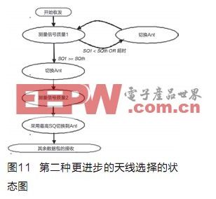
It is possible that when the antenna is selected due to a valid signal indication, its signal quality may still be worse than the best signal, because the measurements made on the antenna may be occupied by noise before the packet arrives. When the first effective signal quality indicator is generated, before selecting the antenna with the highest signal quality, the EZRadioPRO antenna diversity algorithm will first detect other antennas to see if there is a higher signal quality.
Exchangeable AC plug models power adapter,interchangeable plug power adapter,multiple plug power adapter,interchangeable plug power supply 5V 7V 9V 12V 15V 16V 19V 21V 25V 30V 36V.
The 15V interchangeable plug power adapter was made from high quality fireproof ABS+PC with highlighted surface treatment, featuring great grip, high strength, anti-shock, bumps-resistant,to ensure high quality.This 15v Detachable Plug Power Adapter comes with built-in intelligent IC and fuse, to offer protection against over-charge,over-voltage,over-heating that ensures a safe use.

15v Detachable Plug Power Adapter
15 Volt Adapter,Ac Adapter 15V,15V Ac Adapter,15V Dc Power Adapter
Shenzhen Juyuanhai Electronic Co., Ltd. , https://www.powersupplycn.com