MAX3507 space-saving EURO-DOCSIS CATV upstream amplifier
Abstract: This application note analyzes the causes of spurious signal interference in CATV upstream amplifiers. The built-in filter of the MAX3507 can suppress these spurious signals. The test data shows that the IP2 spurious signal of the MAX3507 is approximately -68dBc, and the IP3 is approximately -85dBc.
For more information, please check:
The MAX3507 is a unique upstream amplifier. An anti-aliasing filter is integrated to eliminate glitches generated by the upstream modulator DAC. The on-chip filter, coupled with the MAX3507's ultra-small, 28-pin QFN package, creates a compact DOCSIS solution for DOCSIS and EURO-DOCSIS users.
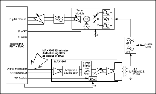
Description of glitch propagation A typical cable modem (Figure 1) requires a complex, differential low-pass filter that is located in front of the upstream amplifier to suppress glitches that occur when the modulated signal is converted from a digital bit stream to an analog waveform. These aliasing glitches occur at the difference between the sampling frequency and the desired output frequency. These glitches can even reach -10dBc relative to the expected output signal amplitude. If these glitches are not filtered out, they will be mixed with the desired signal and produce second and third harmonic components, which cannot meet the requirements of the DOCSIS specification for spurious signals. 
Figure 1. DOCSIS cable modem
When performing digital-to-analog conversion, a standard rule of thumb is that the minimum clock frequency used should be greater than 2.5 times the highest frequency of the analog output. The clock frequency used by most cable PHY / MAC chips is about 3 times the highest output frequency. Figure 2 shows the parasitic interference signals that cable modem designers must consider when determining the attenuation parameters of anti-aliasing filters. In this example, the clock frequency is fixed at 184MHz. The desired signal is generated at three different frequencies: a) 5MHz; b) 35MHz; c) 65MHz. 
Figure 2. Stray components
We are not interested in the situation shown in example a) because all spurious components fall just outside the passband. Example b) indicates that the desired signal frequency is higher, and the spurious signal is closer to the passband. Finally, from example c), it can be seen that in order to meet the requirements of EURO-DOCSIS, the 2nd and 3rd harmonic interference in the frequency band must be lower than -53dBc.
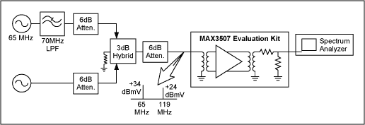
The MAX3507 evaluation board was tested according to the configuration shown in Figure 3. The MAX3507 is designed with a nominal input voltage of + 34dBmV, which corresponds to the "desired signal" shown in Figure 2. In addition to the desired signal, an alias spurious signal with a difference of -10dBc relative to the expected signal is injected into the MAX3507, and the amplitude of the spurious component is recorded. Table 1 lists the performance indicators corresponding to different gains in high-power and low-gain transmission modes. 
Figure 3. Test configuration
FIN1 = 65MHz amplitude is + 34dBmV (continuous wave input)
FIN2 = 119MHz amplitude is + 24dBmV (continuous wave input)
IP2 spurious signal, tested at 54MHz
IP3 spurious signal, tested at 11MHz
| GCW | Transmit Mode | IP2 Spur RelaTIve to Desired Signal (dBc) | IP3 Spur RelaTIve to Desired Signal (dBc) |
| 127 | High Power | -67.3 | -83.2 |
| 119 | High Power | -67.6 | <-85 |
| 104 | High Power | -68.3 | <-85 |
| 84 | High Power | -69.5 | <-85 |
| 64 | High Power | -69.0 | <-85 |
| 74 | Low Noise | -69.5 | <-85 |
| 54 | Low Noise | -70.6 | <-85 |
| 42 | Low Noise | -69.2 | <-78 |
A typical cable modem requires 12 components (inductor and capacitor) behind the PHY / MAC chip to form an anti-aliasing filter. Using the MAX3507 eliminates this filter; providing an upstream driver amplifier that saves space and reduces costs for DOCSIS applications.
1 Hour Fireproof Safes
1 Hour Fireproof Safes are safes that can resist fire attack for 1 hour.
Details:
Special fireproof material stuffing which resist damage;
Seamless molding case;
Heavy duty style doors and hinges;
Anti-drilling, anti-burglar and anti-force;
Yongfa patent: dual system protection;
Fire proof for 1 hour and it can ensure an inner temperature to be less than 177°C(350°F), while exposed to 927°C(1700°F) flames;
Strong hinges and door-bolts;
UL certification passed.
1 Hour Fireproof Safe ,Mechanical Fireproof Safe,Fireproof Gun Safe,High End Fireproof Gun Safe
YONGFA INTELLIGENT TECHNOLOGY SECURITY CO., LTD. , http://www.yongfa-safe.com