Active power filter (APF) can effectively suppress harmonics and current distortion in improving power quality. APF also has the advantages of better grid impedance and harmonic frequency adaptability, real-time compensation of harmonics, and timely compensation of reactive power. .
Active power filter is mainly used to suppress and compensate harmonics in the power grid. The key to accurately and timely compensating harmonics by APF is to acquire the harmonic signals of the load current quickly, accurately, and timely through a certain detection method, and then generate a compensation signal. In order to cancel the harmonics in the power supply and achieve harmonic compensation, the essence of the APF harmonic detection method is to extract the fundamental wave through some method, so as to detect the harmonics, so the active power filter harmonics The key transformation of the detection method is to extract the fundamental component. In this paper, the most fundamental fundamental wave extraction part of the harmonic detection method is studied, that is, the study includes the traditional p iq i method, the average method, and the positive sequence fundamental wave extraction method. This article first studies the theory and then compares the three methods from the simulation point of view on the basis of the theory.
2 Basic Principles of Three Fundamental Wave Extraction Methods
2.1 Traditional ip-iq method based on instantaneous reactive power theory
The working principle of the traditional pi - qi method of instantaneous reactive power theory is shown in Fig. 1. First, assume that the instantaneous voltage and current of the three-phase circuit are ea, eb, ec and ia, ib, and ic, respectively. The 32 C transform obtains two-phase instantaneous voltages ea, eβ and two-phase instantaneous currents ia, iβ in a and β orthogonal coordinates, and a-phase grid voltage ea passes through a phase-locked loop (PLL) and a positive and cosine signal generation circuit. After that, the sine signal sinwt and cosine signal -coswt with the same phase as ae are obtained. These two signals are calculated with ia, iβ and ia, iβ and ia and iβ together with ia, ib, and ic. , ip, iq obtained low-pass filter (LPF) ip, iq DC component
 Then, the fundamental wave components iaf, ibf, icf can be obtained by inverse transformation;
  Is generated by iaf, ibf, icf, so by
  The fundamental wave components iaf, ibf, and icf of the three-phase current can be obtained by the transformation of C-1 and C23. The fundamental current is subtracted from the power supply currents ia, ib, and ic to obtain the harmonic components of the three-phase current i ah, ibh. Ich.
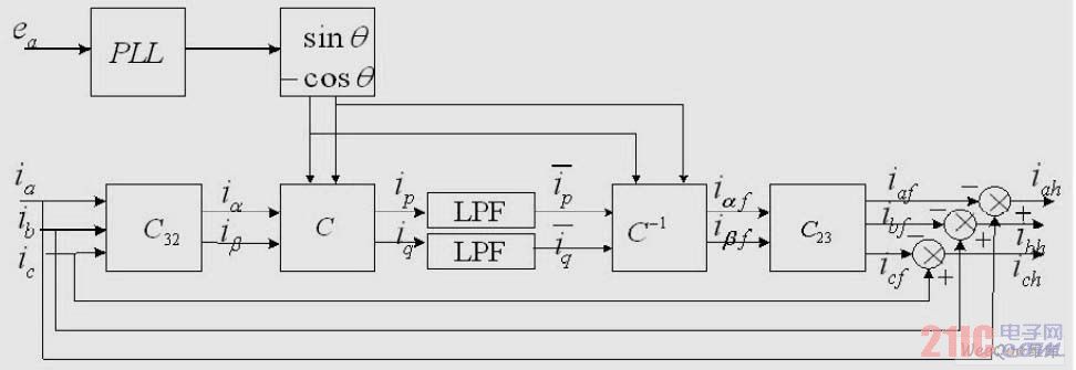
Figure 1 Traditional ip-iq schematic
among them: 
2.2 Average Method Based on Instantaneous Reactive Power Theory
The average method uses the principle of current average, and based on the instantaneous reactive power theory, an improved fundamental wave extraction method based on the traditional pi-qi method is established. The most critical part of the method is to extract the DC component with the average value. The established module separates and obtains the direct current corresponding to the fundamental component, and then proposes the corresponding fundamental component. The block diagram of the average module is shown in Figure 2. The block diagram includes the integration, delay, subtraction, and gain blocks, where T is the power cycle and the output of the delay block is the value of the current integration delay T/6.
The whole working principle diagram of this method is compared with the traditional ip-iq method. It only replaces the LPF with the module shown in Figure 2. 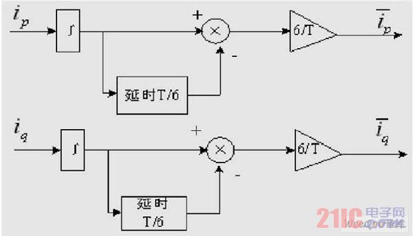
Figure 2 Integral delay gain frame in the mean method
The symmetrical three-phase load current is transformed by Fourier decomposition into the following equation: 
From the above equation, it can be seen that in addition to the DC component in ip and iq, it can also be seen that the period of the AC component is 1/6 of the power cycle, that is, the average value of the AC component in 1/6 power cycles is 0. Therefore, the dc and iq DC components ip and iq can be obtained by the mean value algorithm. The average module formula algorithm is as follows: 
2.3 Positive sequence method
The whole block diagram of the positive sequence method is shown in Fig. 3. This method only uses a positive sequence fundamental wave extractor module instead of the LPF, PLL and coordinate transformation in the traditional ip-iq method. The basic principle of the positive sequence fundamental wave extractor is to obtain the expression (6) by the Laplace transform of the input signal source. When the input signal source contains other harmonic components in addition to the fundamental wave component, the equation (6) The operation can obtain the amplitude integrated signal of the fundamental sinusoidal signal, so this type of operation is frequency selective. 

Fig. 3 Schematic diagram of positive sequence method
The positive sequence fundamental wave extractor block in this block diagram is shown in Figure 4, where K is the scale factor. 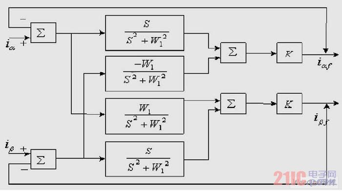
Figure 4 positive sequence fundamental wave extractor module diagram
3 The establishment of a simulation model
The principles and algorithms of the above three fundamental wave extraction methods are the basis for establishing a simulation model. Firstly design the three-phase/two-phase transformation matrix simulation module as shown in Fig. 5, that is, select the adder and etc. in the common module library of Simulink or select the M function module to construct the transformation. Select the simpler former to build the simulation model. .
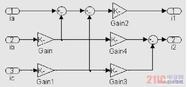
Figure 5 Three-phase/two-phase transformation
The power input module is divided into three-phase symmetrical and distorted power supply when the load is divided into symmetrical and asymmetric full-control rectifier bridge. Here, the signal source modeling when the power supply has distorted three-phase asymmetric load is given. Figure 6 shows.
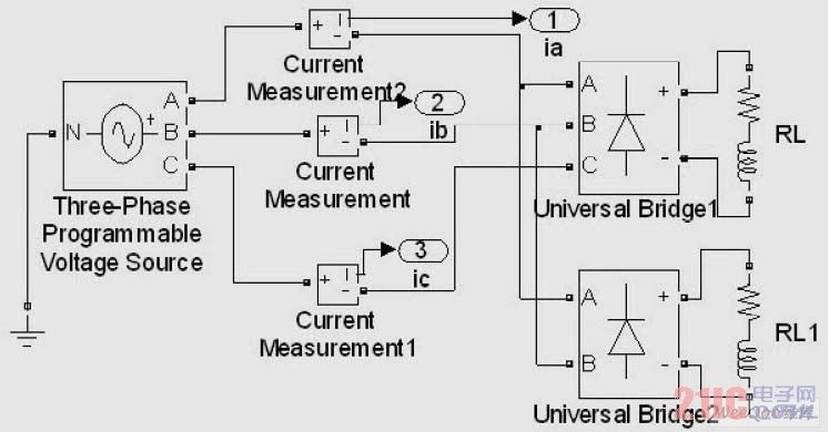
Figure 6 Signal Model with Distorted Asymmetric Loads
Table 1 Power supply voltage, resistance and other parameters. 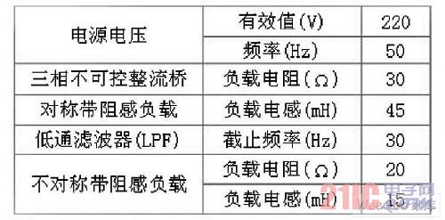
From the above sub-modules and the above schematic block diagram, the entire simulation model of the three fundamental wave extraction methods can be established. The average module can be composed of an integrator, a fixed time delay, and a signal gain module in a continuous system module library. The positive sequence fundamental wave module can use the integral module in the Simulink tool to establish the entire simulation model according to the above schematic diagram.
Power supply voltage, load, and LPF parameters are shown in Table 1.
4 Simulation Results and Comparison
4.1 Simulation Results
Based on the simulation models of the above three fundamental wave extraction methods and the parameters set forth in Table 1, the simulations are based on the simulations of the three-phase symmetric load with undistorted power supply and the three-phase asymmetric load with distorted power supply respectively. The current waveforms are as follows. Figure 7 shows the mains current and the fundamental currents obtained by various methods when the power supply is symmetric with no distortion. 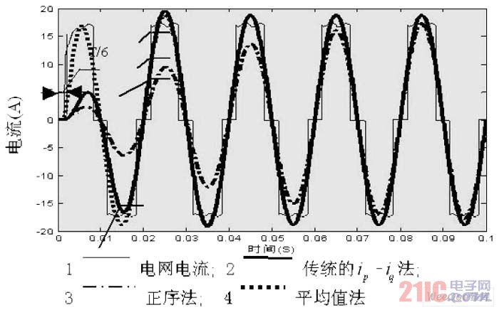
Figure 7 A-phase grid current and fundamental current when the power source is undistorted symmetrically
It can be seen from Fig. 7 that the fundamental current waveform obtained by the positive sequence method tends to stabilize after two cycles, and the fundamental wave separated in the first two cycles is not complete; the fundamental wave obtained by the traditional ip-iq method is after one cycle. It tends to be stable and close to a sine wave; the fundamental waveform obtained by the average method tends to sinusoidal waveform in the first cycle, increasing the overall delay to 1/6 power cycles, and after two cycles The fundamental waveform obtained by the method completely overlaps. The simulation test chart strongly validates the effectiveness and feasibility of the three methods for fundamental wave extraction under symmetric load without distortion.
The simulation waveform in Fig. 8 is the power grid current and the separated fundamental current waveform with 5 amplitude zero and 7 negative sequence harmonic currents of a certain amplitude added to the power supply voltage and asymmetrical load. Both the ip-iq method and the positive sequence method can effectively separate the fundamental wave. After two cycles, the fundamental wave of these two methods is completely close to the sine wave and coincides, and the positive sequence method is more accurate. In this case, the average method has better real-time performance, but it has poor real-time performance compared with symmetric ones. Since the power grid has distortion, the overall delay is increased to close to 1/6 of the power cycle, which is slightly larger than T/6. , but the fundamental wave extraction is less thorough, the waveform is not close to a sine wave or even contains a small amount of distortion. 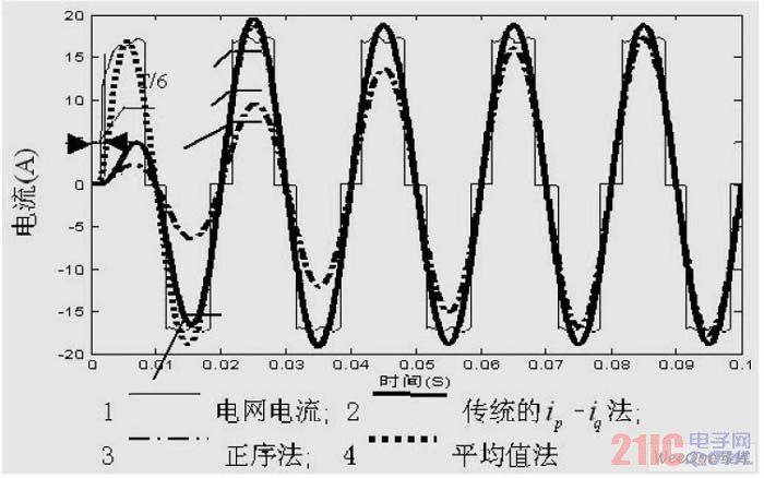
Figure 8 A-phase grid current and fundamental current with distorted asymmetrical loads
4.2 Comparative Analysis
Comparing and analyzing the principles of the three methods, the difference between the average method and the traditional ip-iq method lies in that the LPF in the traditional ip-iq method is replaced by the average module, which makes the filter algorithm simpler and at the same time Filter effect. The difference between the positive sequence method and the aforementioned two methods is that the positive sequence fundamental wave module is used instead of the LPF in the traditional ip-iq method, and the average value mathematical module is not used. This method is aimed at the fundamental wave extraction method based on the instantaneous reactive power theory. Some defects, that is, the filtering control algorithm based on the instantaneous reactive power theory based on the fundamental wave extraction method is complex, and the reactive power components filter out incomplete defects. Therefore, a positive sequence fundamental wave extraction method is used to make up for these deficiencies. The positive sequence method has the advantages of being insensitive to grid frequency deviations, accurate extraction of positive sequence fundamental signals, and the like.
Comparing and analyzing the simulation waveforms of the three methods, the average method does increase the overall delay to 1/6 of the power cycle. The positive phase delay extracted by the positive sequence method is slightly larger and tends to stabilize after two power cycles. It can still accurately and effectively extract the fundamental current when the power supply has distorted three-phase asymmetrical loads, and the accuracy is high.
In summary, the comparison of various performances of the three fundamental wave extraction methods is shown in Table 2.
Table 2 Comparison of Three Fundamental Wave Extraction Methods 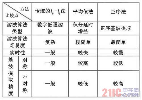
5 Concluding remarks
This paper starts with the three fundamental wave extraction methods of active power filters, focuses on the theory of ip-iq based on instantaneous reactive power, and then analyzes how to extract the fundamental wave components and how to extract the fundamental wave components. Pros and cons. Based on the theory of the three fundamental wave extraction methods, the fundamental wave extraction of the active power filter was simulated using MATLAB/Sinmulink, and the three simulation waveforms were compared. The simulation results show that three methods can effectively extract the fundamental wave in real time when the grid voltage has and without distortion and the load is symmetrical. The best real-time performance is the average method, followed by the traditional ip-iq method, positive sequence. The fundamental wave extraction method is the worst. This paper makes some comparisons between the three fundamental wave extraction methods from the perspective of simulation and theoretical algorithms, and can be used as a theoretical and experimental basis for the fundamental wave extraction and compensation of harmonics in active power filters.
Pogo pin CO.,Ltd , http://www.nspogopin.com