At present, smart cars with automatic driving functions are attracting more and more attention. The smart car is equipped with various sensors to collect road condition information, and can realize adaptive cruise through computer control, and it is fast, stable, safe and reliable. Smart cars can not only work in dangerous, toxic and harmful environments, but also achieve safe driving through computer control, which can greatly reduce the incidence of car accidents. The key to the design of smart cars is the collection of road condition information. The traditional schemes mostly use infrared photoelectric sensors. This scheme not only has a large noise, but also has a complicated connection circuit with the main control CPU and a slow transmission rate. The smart car system studied in this paper selects the TSL1401CL linear CCD image acquisition module. The module is connected with the main control CPU by serial communication. It not only has simple circuit, stable performance, but also fast acquisition speed. Through experimental tests, the smart car designed in this paper can realize intelligent driving based on the collected images to analyze the front path and obstacles, which has strong practical value and market prospect.
1 system design ideas
After investigation and analysis, we used MC9S12XS128 MCU, TSL1401CL linear CCD image acquisition module, voltage regulator chip and LCD OLED and other peripheral devices to design and develop this smart car system. The MC9S12XS128 high-speed single-chip microcomputer is a new 16-bit high-performance high-speed single-chip microcomputer from Freescale. It has rich interfaces, low power consumption and powerful information processing capability. It can analyze the path and obstacles in front of the car in a timely manner, with rapid processing and stable performance. In order to improve the speed and quality of road image acquisition, we chose the TSL1401CL linear CCD image sensor. TSL1401CL has the advantages of low power consumption, stable performance, high sensitivity and fast response. The working process is to convert the optical signal of the road condition into analog current, then the analog current is amplified and then converted into digital signal by A/D conversion. Finally, the serial port is passed through the serial port. Send to the main control CPU. The CPU of the smart car is analyzed and processed according to the information collected by the CCD, thereby realizing automatic control, obstacle processing and path detection of the system. In the software design, we adopt advanced PID (proportional, integral, derivative) algorithm, and its operation parameters can be set in time according to the dynamic characteristics of the process. Through the PID algorithm, the fuzzy PID algorithm is used to realize the precise automatic control of the steering and speed control of the smart car. In addition, there is a good obstacle avoidance function, which realizes the full intelligent security control.
2 system hardware design
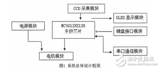
The project adopts modular design and development, mainly including CCD acquisition module, power module, motor drive module, vehicle speed control module and the overall design block diagram of the system.
2.1 CCD acquisition module
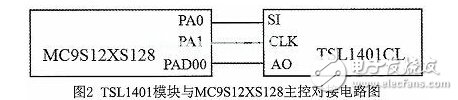
The module uses the TSL1401CL linear CCD image sensor, which consists of a 128&TImes1 photodiode array, associated charge amplifier circuitry, and an internal pixel data retention function that provides all pixels that integrate both start and stop times. For the driving and use of the TSL1401CL linear sensor, this project uses the PA0 and PA1 pins of the MC9S12XS128 to send a square wave signal to the CLK and SI pins at a specific timing. The AO pin of the TSL1401CL will output 128 pixels in sequence. The analog signal is given to the MC9S12XS128, and its circuit is shown in Figure 2. We found through testing that the output signal of the sensor is closely related to the ambient light. The AO output value during the day is much higher than that at night, and the difference between the light and the backlight is also large. The incandescent light and the daylight light line are very different. The same lens or signal amplification factor will inevitably be unable to adapt to various environments. It will often appear too weak or signal saturation, and the adaptability to the environment is very weak. For this, the dynamic exposure time can be used by software or the magnification of the op amp can be dynamically changed by the single-chip microcomputer. .
2.2 Power Module
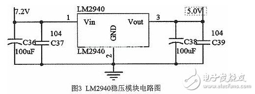
The system consists of different modules. Each module operates at a different voltage. The power required by each module must also be considered in the design. A battery detection system is also needed to visualize the battery. The power requirements for smart cars include 5V, 7.2V, and so on. For the 5V power supply design, we chose LM2940-5. Compared with the 7805, the 2940 has the advantage of low-dropout voltage regulation, and its voltage difference is less than 500mV. This ensures that the battery and the sensor can work normally under low voltage conditions. The output current of the LM2940 can reach 1A, enough to supply the amplifier circuit and keyboard display circuit. The circuit design of the LM2940 module is shown in Figure 3.
2.3 Motor drive module
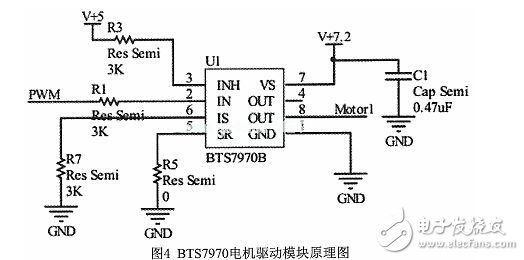
The drive circuit provides control and drive for the smart car drive motor. This part of the circuit is designed to pass large current as the main indicator. The basic principle of the drive circuit is the H-bridge drive principle. The current popular H-bridge drive circuits are: H-bridge integrated circuits, such as MC33886; integrated half-bridge circuits, such as BTS7970 and H-bridges built by MOS tubes. For the design of this system, we chose the BTS7970 with better performance as the main chip of the motor drive module. The working circuit diagram is shown in Figure 4.
2.4 Speed ​​Control Module
The speed of the smart car mainly adopts incremental PID control and positional PID control, which combines fuzzy control with PID control to enable the smart car to travel smoothly and quickly on the track. The intelligent car speed control system takes the XS128 MCU as the core, and the MCU gives the motor a given speed, ie the theoretical speed, establishes a fuzzy PID controller, and uses the fuzzy PID controller to control the motor speed, that is, controls the actual speed of the smart car. The photoelectric encoder is used to measure the actual vehicle speed of the smart car, and the actual vehicle speed is fed back to the fuzzy PID controller to form a closed loop negative feedback loop.
2. 5 steering control module
The steering gear SD-5 of the smart car adopts positional PD control. Because the steering precision of the steering gear is high, different PWM duty cycles correspond to different rotation angles of the steering gear, so open loop control is adopted. When the trolley is in the straight lane, the steering gear is squared; when the trolley is in the curve, the curvature of the curve is larger, the larger the corner angle of the steering gear is, and the difference between the weighted average deviation of the image and the center of the image is used as the control amount.
3 system software design
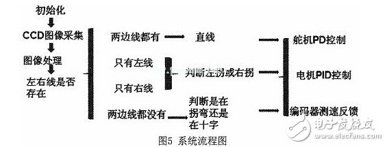
The system software is written in C and compiled with the Code Warrior IDE. The idea of ​​software design is to drive linear CCD optics to acquire single-line image information, to process the acquired image to determine the position of the car and to determine the route in the direction of the car when traveling, and then to convert the processed information into a change. The PWM amount is sent to the steering gear and the motor and the encoder processing module to control the direction of travel of the trolley and the speed of the vehicle. The system flow chart is shown in Figure 5.
4 Summary
For the design and development of the smart car system of this project, we selected MC9S12XS128 high-speed single-chip microcomputer as the control core, obtained the TSL1401CL linear CCD acquisition information and angle measurement information through A/D conversion method, and used the fuzzy PID algorithm to realize the straight-forward, steering and speed of the car model. Control plan. MC9S12XS128 is the core of the whole system information processing and control commands. The linear CCD sensor is used to identify the running path of the car. The collected information is compared in real time on the MCU. The PID control algorithm is used to control the speed and steering of the car, thus realizing the intelligence of the car. Autopilot. The advantage of this solution is that the circuit is simple and the system performance is stable. After testing, this smart car can realize intelligent automatic driving under complicated road conditions.
Gesture control
Smoke sensor
Auto cleaning
Sensor touch control
Energy saving
Top Mounted Range Hood Black,Silence Range Hood,Powerful Range Hood,Automatic Range Hoods
JOYOUNG COMPANY LIMITED , https://www.globaljoyoung.com