introduction
Due to the different levels of audio signals such as advertisements, news, radio dramas, songs and broadcast programs of the self-running channel, the audio signal is suddenly large and small when the program is broadcast, which seriously affects the user's listening effect. At the time of retransmission, due to the transmission distance and the like, there is also a phenomenon in which the signal size is different at the output end of the signal. In the past, the limiting mode was adopted for large audio signals, that is, the limiting output of large signals was performed, and the small signals were not processed. In this way, the audio signal is still too small, and the user can adjust the volume by himself, which also affects the user's listening effect. With the rapid development of electronic technology, computer technology and communication technology, digital signal processing technology has been widely used in various fields such as people's lives. Among them, speech processing is one of the most active research directions of digital signal processing, and is widely used in IP telephony and multimedia communication. The voice processing can be realized by a general-purpose digital signal processor DSP and a field programmable gate array (FPGA). The DSP implementation method has the advantages of simple implementation, strong program loadable line, fast processing speed, and the like, especially in the audio processing of TI TMS320C54X series. It has a good cost performance, can solve complex algorithm design and meet the real-time requirements of the system, and is widely used in many fields. On the basis of DSP, the AGC algorithm processing of the audio signal can keep the output level within a certain range, and can solve the problem of unbalanced audio of different programs.
Audio signal acquisition
TI DSP chip TMS320V
The C5402 features a unique 6-bus Harvard architecture that enables six pipelines to operate simultaneously with an operating frequency of 100 MHz. Seamless connection to AIC23 is achieved by using the VC5402's two multi-channel buffered serial ports (McBSP0 and McBSP1). The VC5402's multi-channel buffered serial port adds a 2K buffer to the standard serial port. Each time the serial port sends data, the CPU automatically sends the data in the send buffer; when receiving the data, the CPU automatically writes the received data to the receive buffer. In the automatic buffer mode, it is not necessary to send an interrupt every time a word is transmitted, but each time a buffer boundary is passed, an interrupt is generated to the CPU, thereby reducing the impact of frequent interruptions on the CPU.
The audio chip uses TLV320 AIC23, which is a high-performance stereo audio A/D and D/A amplifier circuit from TI. The AIC23's analog-to-digital conversion and digital-to-analog conversion components are highly integrated inside the chip, using advanced oversampling techniques. The external hardware interface of AIC23 is divided into analog port and digital port. The analog port is used to input and output audio signals, and supports line input and microphone input. There are two sets of digital interfaces, one of which is a digital control interface composed of /CS, SDIN, SCLK and MODE. AIC23 is a programmable audio chip. The control word of the chip is written into the internal register of AIC23 through digital control port, such as sampling rate setting, working mode setting, etc. There are 12 registers. The communication between the audio control port and the DSP is mainly realized by the multi-channel buffer serial port McBSP1.
AIC23 communicates with the DSP's McBSP0 through the digital audio port, the DSP acts as the host, and the AIC23 acts as the slave. The host provides a transmit clock signal BCLKX0 and a transmit frame sync signal BFSX0. In this mode of operation, the receive signal BCLKR0 and the receive frame sync signal BFSR0 are actually provided by the host. Figure 1 shows the interface between the AIC23 and the VC5402.
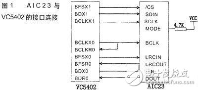
The AIC23's digital audio interface supports the S (Universal Tone Format) mode and also supports the DSP mode (specifically connected to TIDSP), where DSP mode is used. When the DSP mode is working, its frame width can be one bit long.
Figure 2 is a detailed circuit diagram of audio signal acquisition.
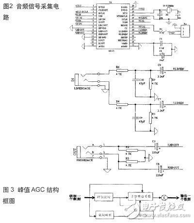
The design and wiring of the circuit is a very important part of the signal acquisition process, and its effect is directly related to the quality of the late signal processing. For DSP high-speed devices, the external crystal can reach hundreds of megabytes after being multiplied by the internal PLL. This requires the signal lines to go along the isometric lines and draw multi-layer boards to eliminate electromagnetic interference and signal reflections. Under the premise of two-layer board, you can take the principle of widening the cross line between the top and bottom layers, widening the width of the power and ground lines, and the power line into a "tree type", analog area and digital area. Effect.
Implementation of audio AGC algorithm
AGC algorithm
The control method that automatically adjusts the gain of the amplifying circuit with the change of the signal strength is AGC-automatic gain control. The implementation of the AGC can be a hardware circuit, that is, an AGC closed-loop electronic circuit, or a software algorithm. This article focuses on the use of software algorithms to achieve AGC audio signals.
The audio AGC is an audio automatic gain control algorithm, more accurately a peak automatic gain control algorithm, which is a mechanism for automatically and dynamically adjusting the gain according to the input audio signal level. When the volume (whether the captured volume or the reproduced volume) exceeds a certain threshold, the signal is clipped. Limiting means that the output of the audio device no longer changes with the input, and the output essentially becomes a horizontal line at the maximum volume position; when it detects that the audio gain reaches a certain threshold, it automatically reduces the gain. Avoid clipping. On the other hand, if the captured volume is too low, the system will automatically increase the gain. Of course, the gain adjustment does not cause the volume to exceed the value set by the user in the adjustment wizard. 3 is a structural block diagram of an audio AGC algorithm.
Implementation process of AGC algorithm
First, the audio data is obtained from the serial port. It is a 16-bit integer. Generally speaking, these numbers are relatively small. The input audio data is projected into a fixed interval by the AGC algorithm, so that no matter the number of data points input. The value size is mapped to this space in equal proportions. On the one hand, the maximum value of the obtained audio data is compared with the original peak value, and a new gain coefficient is calculated if a new peak appears; on the other hand, a new peak is acquired in a certain period of time, and the peak has the detection performance. And compare with the original peak, and then calculate the new gain factor. This gain factor is relatively stable. When the volume is increased, the peak value of the signal is automatically increased, and the gain coefficient is automatically decreased. When the volume is decreased, the new peak is reduced and the original peak is replaced, so that the peak value is decreased and the gain coefficient is increased. The last output data is multiplied by the new gain factor and mapped into the projection interval of the audio signal input.
4 is a flow chart of a program of an audio signal AGC algorithm.

AGC_Coff is the initial gain coefficient, the initial value is 1; maxAGC_in is the gain peak, the initial value is 0; time is the sampling point count, the threshold is 4096; AGC_in is the new audio data, MAXArrIn is the new audio gain peak; [-20000, 20000].
The software part of the entire system is a 5-person module. System main function main ( ), CMD file, interrupt vector table, DSP5402 header file and library function rtdx.lib developed for C language. The main function part is the core, which mainly includes: DSP device initialization, MCBSP1 initialization, MCBSP0 initialization, AIC23 initialization (internal 12 programmable register settings) and algorithm programs.
In the CCS2.0 integrated development environment, using *.c language and *.asm language
Write the program in a combined way. The compiled program *.c, *.asm and the linker *.cmd file are compiled and linked to generate the execution target file *.out, and the execution target file *.out is downloaded to the system board through the emulator, after debugging, compiling and Run, input music to the system board as audio source.
Conclusion
This complete audio signal acquisition and processing system has been used in practical audio equipment.
High Power Light,Led High Power Lamp,High Power Led Light,Led High Power Lamp Price
Changxing Fanya Lighting Co.,Ltd , https://www.fyledlights.com