0 Preface
This article refers to the address: http://
With the increasing number of residents' car ownership and the accelerated pace of people's lives, the number of traffic accidents caused by fatigue driving has also increased year by year. The number of deaths caused by traffic accidents in the world is 600,000 per year, and the direct economic loss is about $12.5 billion. 57% of these accidents are related to driver fatigue driving. Therefore, research and development of a non-contact fatigue driving monitoring system has great social and practical significance.
1 system hardware design
The early warning system is mainly composed of five parts: a microcontroller, an image data acquisition module, an LED warning module, a communication interface and a power supply module, as shown in FIG. 1 . A 32-bit ARM processor is used depending on processing speed and accuracy requirements. In order to reduce the impact on the driver and better realize the non-contact type, this paper selects the CMOS camera OV3640 module with 3 million pixels. Compared with CCD, CMOS has high sensitivity, high resolution, low power consumption and low cost. Advantage.
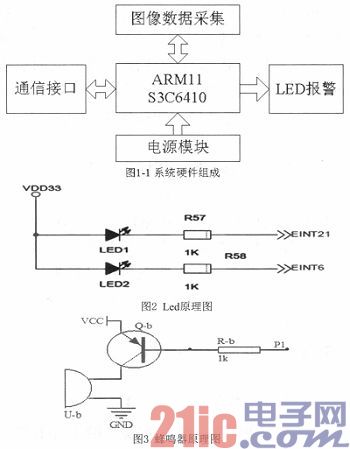
Since the Rea16410 development board does not have a buzzer and other sounding devices, and the buzzer sounds and the LED light is similar in principle, this article uses LED lighting alarm. Figure 2 is a schematic diagram of the development of LEDs in the board. Just give the latter pin a low level to make the LED glow red and alert. Here is a brief introduction to the principle of buzzer sounding. The schematic diagram shown in Figure 3 gives the P1 pin a low level to make the buzzer sound.
2 system software design
2.1 Construction environment development
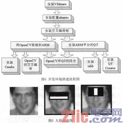
If the system hardware is the skeleton and the body, then the software algorithm is the idea. Before you can write a program, you need to establish a software development environment. The flow chart of the software development environment is shown in Figure 4.
2.2 Adaboost algorithm
The basic idea of ​​the Adaboost algorithm is to use a large number of general classifiers to superimpose a strong classifier with strong classification ability.
The implementation of the Adaboost algorithm uses the rectangular feature of the input image, also known as the Haar feature. Some features of the face may be simply depicted by rectangular features. Demonstrate with Figure 5.
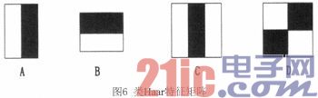
The two rectangular features in the above image represent some features of the face. For example, the middle one indicates that the color of the eye area is darker than the color of the cheek area, and the right one indicates that the sides of the nose are darker than the nose. Similarly, other targets, such as the eyes, must be positioned in order to obtain information on the image of the eye. There are many existing methods of eye localization, methods based on skin color model, gray projection method, template-based method, neural network-based method, feature extraction and the like. The system uses the Adaboost algorithm to construct a stacked classifier based on Haar-like features for human eye localization. The Haar-like features usually consist of 2 to 4 rectangles, as shown in Figure 6.
2.3 Using Haar to Identify Human Eyes
The Haar feature classifier for the face is an XML file that describes the Haar eigenvalues ​​of the face. Haar features can also describe the lips or other objects of the eye.
OpenCV already comes with a Haar feature classifier for faces. Under /usr/locaI/Opencv-2.4.3/data/haarcascades. Haarcascade_frontalface_al t.xml and haarcascade frontalface alt2.xml are both Haar classifiers for detecting faces, haarcascade_eve.xm l and haarcascade eye tree eyegla sses.xml are used to detect human eye Haar classifiers, this haarcascades directory There are also people's body, the Haar classifier of the lips. Figure 7 is the detected face.

2.4 Using the threshold method to judge the fatigue state
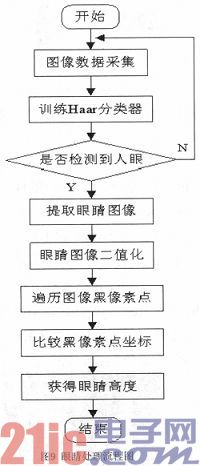
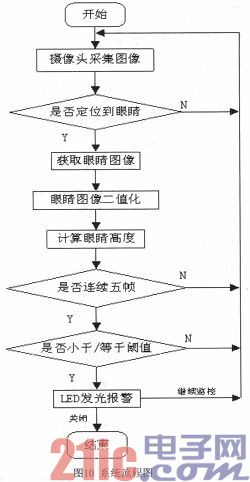
The above algorithm locates the eye and intercepts it, uses the sobel to implement edge detection and then binarizes the image, temporarily stores the binarized image in a temporary folder, calls the image in the temporary folder, and for loops through the image pixels, comparing The black pixel coordinates are obtained and the upper and lower maximum drop values ​​are obtained, from which the corresponding height threshold is given. When the detected eye height value is equal to or smaller than the set eye height threshold, if the height value of the eyes of five consecutive frames is equal to or smaller than the threshold, the system determines that the driver is in a fatigue state. The entire system flow is shown in Figure 9.
3 system overall design
3.1 System Design Process
The entire system design process: 1) detection camera and development board; 2) acquisition of images. Get the driver's avatar in real time through the camera; 3) Build a software development environment. Porting QpenCV to ARM, installing QT under Linux; 4) handling of human eyes. Firstly, the Haar classifier in OpenCV is used for eye recognition and positioning, and then the extracted image of the eye region is binarized. Finally, by scanning the black pixel of the binarized image, the highest and lowest points of the eye are obtained. The coordinates of the point, the height value of the eye is calculated by the coordinate difference; 5) the fatigue is judged. When it is detected that the height value of the eye is less than or equal to the set eye height threshold, it is recorded. If the height values ​​of the eyes of five consecutive frames are less than or equal to the threshold, it is determined that the driver is in a fatigue state; 6) an alarm. LED lighting alarm; 7) Programming the GUI for fatigue driving. The flow chart is shown in Figure 10.
3.2 System GUI design
In the interaction between humans and computers, there is a layer, which is what we call an interface. GUI (Graphical User Interface) is a graphical user interface that uses a graphical interface instead of a text interface. Its role is to achieve a good interaction between the user and the computer.
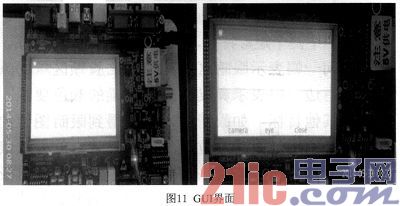
The application compilation environment is Qt Creator. When using the fatigue warning system, the following button showing the begin will appear when you open it. When you touch the start button, the system will enter the fatigue monitoring program. When the monitoring is over, the development board will give the led light an early warning. . When you end the warning system, just touch the “close†button on the interface to return to the begin interface. As shown in Figure 11.
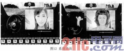
After touching the eye system to enter the main interface, you can observe through the display area at the bottom of the interface. When the driver closes his eyes, the bottom of the system will get an image of the closed eye state. When five consecutive frames of images are closed, the system will alarm. Figure 12 system interface.
4 Conclusion
This paper is based on the ARM processor design of the driver fatigue warning system, based on the establishment of a good ARM platform development environment, using QT technology to design the system interface, and finally based on OpenCV transplant driver fatigue warning algorithm. The early warning system designed in this paper has the following advantages or features: 1) Using the powerful ARM series processing platform as the hardware environment of the system, compared with other architectures such as DSP+ARM, the system performance is similar when the processing performance is not much different. The hardware cost is greatly reduced, which is more in line with economic requirements. 2) Compared with devices such as EEG, electro-oculogram, and electrocardiogram that need to contact the driver's body, this design uses a camera to achieve non-contact and is more convenient to use; 3) According to the system The characteristics of each processing module, using a combination of multiple algorithms to achieve the system, more real-time, high efficiency.
Dc Motor Current Control,High Current Dc Motor Controller,High Current Dc Motor Speed Controller,High Current Dc Controller
Jinan Keya Electron Science And Technology Co., Ltd. , https://www.keyaservo.com