challenge
This article refers to the address: http://
Whether it is a traditional car or a new energy car, a safe, green and comfortable car electronic system is a common appeal. Car safety includes zero failure, functional safety and self-diagnosis modules. Environmentally friendly means reducing vehicle weight through the use of the vehicle network. In order to reduce energy consumption, it also includes the use of environmentally friendly materials and processes; powerful graphic image processing technology, intuitive and friendly human-machine interface to provide drivers with a comfortable driving experience.
The technical content and quantity of electronic devices in automobiles is an important indicator of car performance. As people's demands for driving comfort, safety, entertainment and economy become more and more demanding, the automotive electronic system becomes more complicated, and the number of electronic devices in the automobile is also increasing. Many features such as ABS, electronic ignition systems, airbag protection and parking sensors are now standard, and this is not enough, as people's pursuit of more precise car control and entertainment enjoyment has not stopped.
However, automotive electronics designers face numerous technical challenges during the system design process, including designing various circuit protection methods to overcome electrical hazards. The three main sources of electrical hazards in these systems are electrostatic discharge (ESD), lightning, and switching loads in power electronics. Overcoming transient surges that destroy vehicle electronics is the biggest challenge in the design process.
solution
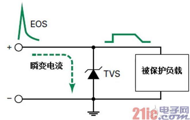
Automotive electronic circuit protection includes the elimination of transient surges as it will damage control units, entertainment system electronics, sensors, injectors, valves, motors, 12/24/42V transmission systems and hydrolysis controllers.
What does the Littelfuse Transient Voltage Suppressor (TVS) protect?
As shown in Figure 1, the Lite transient voltage suppressor provides protection for the four main types of vehicles: safety systems, high-performance systems and low-radiation, comfort and convenience systems, and hybrid vehicle systems.
In modern car design, all in-vehicle electronics are connected to batteries and alternators. As shown in Figure 2, the output of the alternator is unstable and requires further commissioning before it is used to power other systems in the vehicle. Today, most alternators have Zener diodes to prevent surge voltages caused by load fluctuations; however, these are not enough. During startup or switching of inductive loads, because the battery is disconnected, resulting in spikes or transients that, if not corrected, are transmitted along the power line, causing personal electronic devices and sensors to malfunction or permanently destroy the vehicle's electronic system, thereby Affect overall reliability.
Automotive Transient Surge (Non-ESD) Standard TPSMA6L
Littelfuse is a leading supplier of transient voltage suppression diode products. The LittelfuseTPSMB and TPSMA6L system transient voltage suppression diodes provide secondary transient voltage protection, transients due to load changes, and other transient voltage events for sensitive electronics. The automotive grade TVS series offers superior electrical performance in a small package, allowing designers to upgrade their circuit protection without having to change their existing design packaging or provide a more robust protection solution in the new circuit layout.
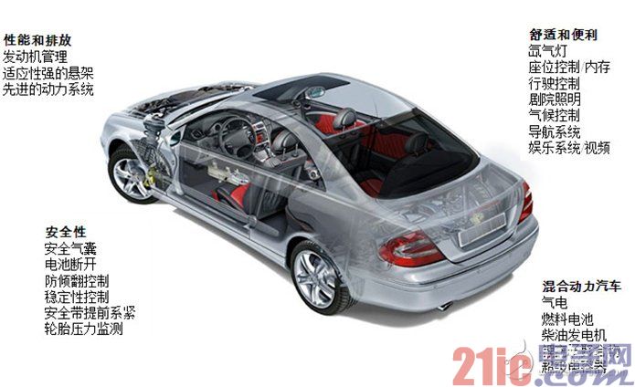
Figure 1 Vehicle system is subject to transient surge damage
Alternator / voltage regulator assembly (actual circuit full wave rectification)
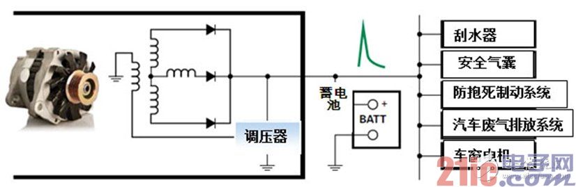
Figure 2 Most of the transients in the vehicle's electrical system are caused by alternators
In 12V/24V systems, voltage fluctuations caused by load changes require high-energy transient voltage suppression diodes.
The automotive market has two main criteria that outline the protection of transient surges: JASO and ISO7637-2 (surge) tests in Japan, the US and international markets. JASO A-1 describes the test conditions for the 14V vehicle system; JASO D-1 describes the test conditions for the 27V vehicle. The following test standards are international and US test standards, including load changes, switching transients, and electrostatic discharge threats.
International standard ISO 7637:
• Suitable for road vehicles – electrical interference through conduction and coupling.
American National Standard:
• SAE (Institute of Automotive Engineers) J1113
• GM 9105, ES-F2af-1316-AA Ford (Visteon)
More information about the ISO7637-2 pulse:
• Automotive EMC transient requirements
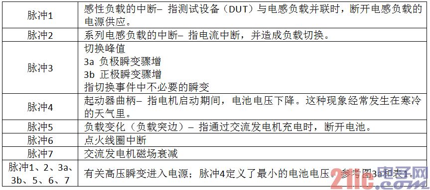
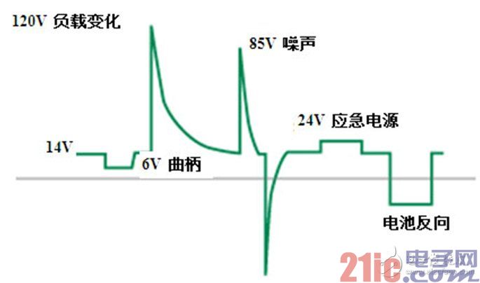
Figure 3a Surge waveforms of different pulses and their sizes
Automotive environmental test level
Table 1 Test level of each pulse ISO7637-2
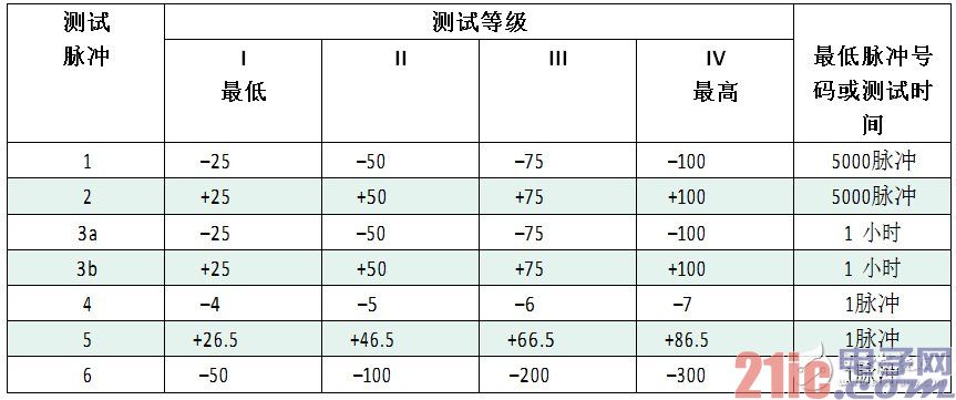
• Four performance levels for each pulse
– different o/c voltage
– negative and positive
– pulse duration 0.1–400ms
– single pulse and pulse train
– Transient voltage suppression and its operating mode
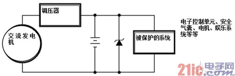
Figure 3b Transient Voltage Suppression Diodes are used in various automotive systems as shunt/transient surge protectors
As shown in Figure 3, the transient voltage suppression diode TPSMA6L15A is placed in front of the electronic control unit, sensor, airbag, controller, motor, etc. When the alternator supplies power to the electronics, the transient voltage suppression diode will prevent unwanted transients, allowing the DC system to operate at 12-14V. Car bus protection
The most popular communication bus standards today are CAN and LIN buses.
The CAN bus (Control Area Network) is an automotive bus standard designed to allow microcontrollers and devices to communicate with one another in a vehicle without the need for a host.
The CAN bus is an information-oriented protocol designed for automotive applications, but is also currently used in other regions such as aerospace, industrial automation and medical equipment.
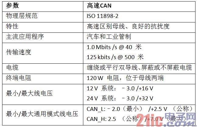
The popular high-speed CAN bus protocol is ISO11898-2, which is suitable for high-speed (1.0Mbps) and medium-speed (125Kbps) applications in harsh environments.
The ISO11898-2 busbar consists of CAN_H and CAN_L data lines and a common ground signal. It has 12V and 24V systems with different bus voltages.
Table 2 High Speed ​​CAN Specifications
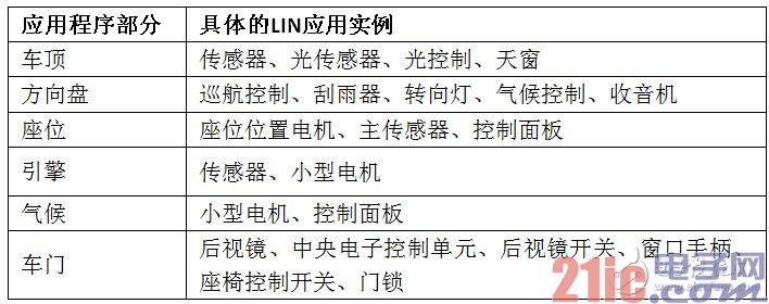
The LIN (Local Area Connection Network) bus standard is a serial network protocol for communication between vehicle components. As the technology and facilities in vehicles grow, the demand for inexpensive serial networks is raised, as the use of CAN buses to communicate the various components in the car is too expensive. European car manufacturers are beginning to use different serial communication topologies, leading to compatibility issues.
The first full implementation of the new LIN specification (LIN version 1.3) was published in November 2002. In September 2003, version 2.0 was introduced to expand its compatibility and provide additional diagnostic features.
LIN can also be used in vehicle power lines with special DC-LIN transceivers, which are common in the automotive world today.
Table 3 LIN Bus Application
Differences between CAN and LIN bus applications
The Control Area Network (CAN) system handles everything from the automatic force steering wheel to the critically driven train engine computer and the communication between the transmissions.
The Local Network Connection (LIN) system handles simple electromechanical functions such as moving power seats and switching cruise control.
Threat to CAN/LIN bus in the automotive world
Since the CAN/LIN bus is a two-wire communication bus for various control and monitoring functions in the car, there is a high possibility that the surge enters the two wires, causing the CAN/LIN transceiver to malfunction. The following are the protection methods for these two buses.
CAN bus protection diagram
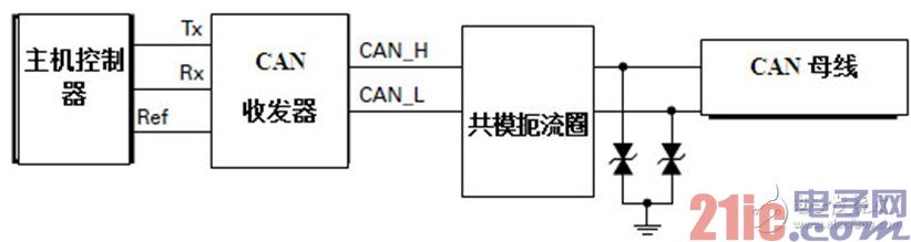
Figure 4 CAN bus protection
As shown in Figure 4, the TPSMB30CA transient voltage suppression diode is designed to protect two CAN busses from common surges (with a 24V system) from surge events. The TPSMB24CA is a 600W bidirectional transient voltage suppression diode with a 25.6V reverse balanced voltage and a 41.4V maximum clamp voltage. It is well understood to protect the CAN bus without weakening the CAN signal. In the 12V CAN system, two TPSMB15CA transient voltage suppression diodes are used instead of the TPSMB24CA.
LIN bus protection diagram
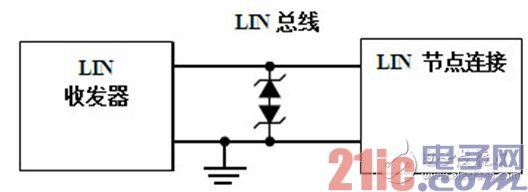
Figure 5 LIN bus protection
The signal range of the LIN transceiver is +24 /–15V and the data rate is 2.4kbps to 20kbps. As seen in Figure 5, a bidirectional asymmetric transient voltage suppression diode configuration is required to protect the two wires in different modes.
The TPSMA6L24A/TPSMA6L15A transient voltage suppression diodes are connected in anti-serial mode to protect both wires in the event of a surge event. The TPSMA6L Transient Voltage Suppression Diode is a 600W device housed in a small DO-221AC package. An alternative solution to the same power handling capability would be to add a TPSMB30CA (bidirectional) to protect the LIN bus. ISO763-2 pulse 5a test
Pulse 5a is tested on a 33V VBR (saturation voltage) transient voltage suppression diode as follows.
Table 5 Reliability Test Report on Lite Transient Voltage Suppression Diode in ISO7637-2 Pulse 5a
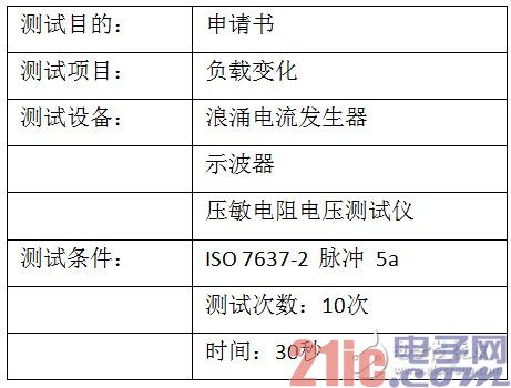
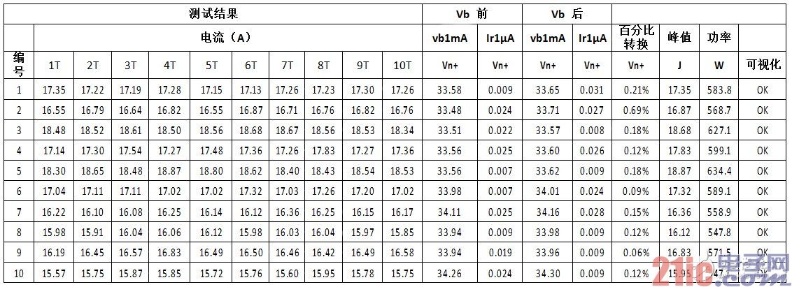
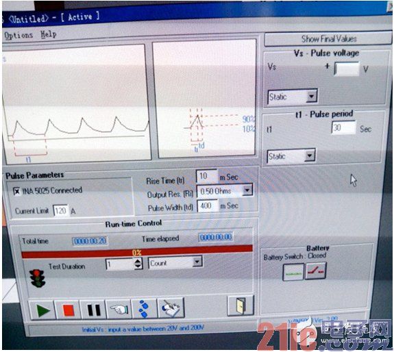
Figure 6 Test waveform and oscilloscope screen
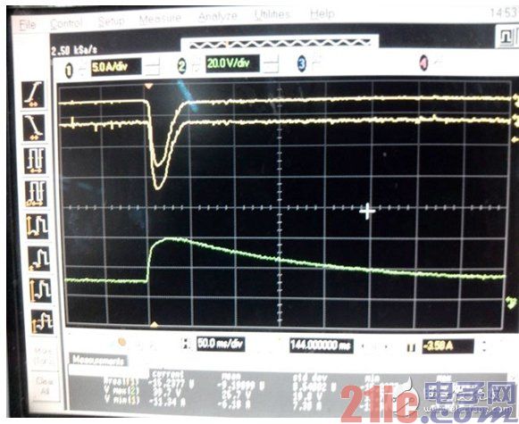
Figure 7 test voltage 30V and current 11.34A
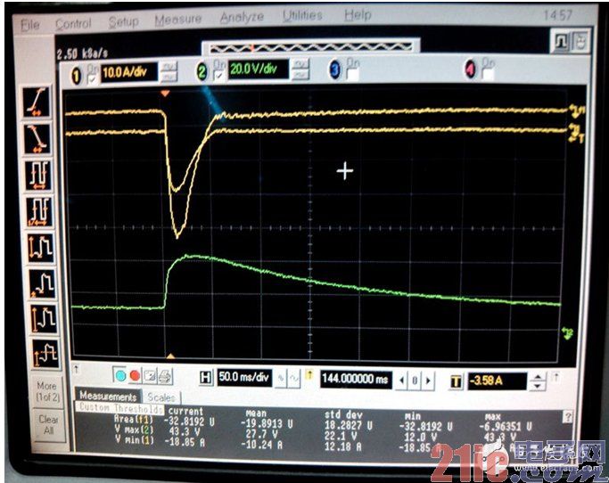
Figure 8 Test voltage 35V and current 18.85A
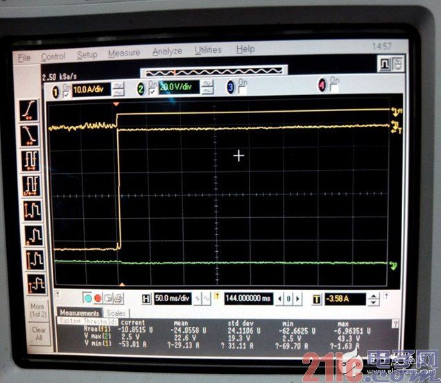
Figure 9 test voltage 36V
The results show that the 33V VBR transient voltage suppression diodes have passed the ISO7637-2 pulse 5 test standard for 10 operations. Before and after the test, the change in startup voltage was very small and negligible (<0.2%).
Transient voltage suppression terminology
Reverse operating voltage
In the case of a unidirectional transient voltage suppression diode, the reverse operating voltage is the maximum peak voltage applied in the "blocking direction" with no significant current. In the case of two-way transients, both directions can be applied. It has the same definition, ie the maximum off-state voltage or the maximum operating voltage.
Starting voltage
Specifies the voltage measured in the DC test current, typically 1 mA. Usually define a minimum or maximum value.
Peak pulse power
Expressed in watts or kilowatts, 1ms pulse width. IPP is multiplied by VCL.
Maximum clamp voltage (VC or VCI)
The maximum voltage measured by the entire protector when subjected to a peak pulse current of the electric power.
Peak pulse current (IPP)
The peak pulse current (IPP) confirms that the transient voltage suppression diode can withstand the maximum current that is not damaged. The required IPP can only be determined by dividing the peak transient voltage by the source impedance. Note that the failure of the transient voltage suppression diode is a short circuit; if the transient voltage suppression diode fails due to transients greater than the data sheet specifications, the circuit is still protected.
PET braided cable Self Closing Wrap braided sleeve
This PET braided cable Self closing wrap braided sleeve consists of flexible, flame-retardant woven polyester that meet RoHS stantard. It possesses good flexibility, fire resistance, abrasive resistance and thermal insulation performance. The sleeving owns smooth surface, bright color, various patterns.
Does not trap heat or humidity Rot-free Self-fitting over many shapes and sizes Self-extinguishing when used to encase Reach, Halogen Free, typical non-flammable wires or cables Fray resistant
Most commonly used on wire harnesses, cable assemblies, flat ribbon cables, tubes and hoses to provide a tough, durable protection in automotive, automatic equipment, railways and panel boards.
Feature & benefits of Braided Mesh Wire Wrap Self Closing Sleeve
1, Economical & easy to install
2, Cut & abrasion resistant
3, 25% edge overlap
4, Halogen free
5, Splice Free
Braided Mesh Wire Wrap
Self Closing Split Pet Braided Sleeve,Self Closing Wrap Cable Sleeving ,Colorful Pet Cable Sleeve,Cable Management Sleeve
Shenzhen Huiyunhai Tech.Co.,Ltd , https://www.hyhbraidedsleeve.com