0 Preface
This article refers to the address: http://
Tire failure is an important cause of sudden traffic accidents during high-speed driving. According to statistics, about 70% of the traffic accidents on the expressway are caused by punctures. Keeping the standard tire pressure and timely detecting the tire leakage is the key to prevent the tire from bursting. Therefore, monitoring the parameters such as tire pressure and temperature is an important guarantee for safe driving. The development and research of the tire tire pressure monitoring system TPMS (Tire Pressure Monitoring System) is an effective technical measure to ensure the safety of driving, and is also an important subject worth studying. TPMS is currently the most popular automobile tire pressure monitoring system. It can automatically and automatically monitor tire pressure and temperature in real-time and dynamic conditions, and perform abnormal phenomena such as low tire pressure, high air pressure, high air leakage and high temperature. Automatic alarms to reduce the incidence of accidents and ensure safe driving. From the system configuration, information such as pressure and temperature can be transmitted and received by the wireless device.
This paper introduces the hardware and software design of the car tire pressure monitoring system based on the Bluetooth chip nRF401. The design uses SPCE061A as the host computer controller to realize the management and output of the pressure and temperature signals of the car tires. The display system and the voice alarm system display the test results in real time and accurately. The system can accurately collect the temperature and pressure inside the tire, and can alarm in time when dangerous conditions occur.
1 hardware design
The tire pressure monitoring system mainly consists of two parts: one part is installed in the tire of the automobile, and the tire emission module is composed of pressure temperature sensor, signal processing unit and RF transmitter. The composition of the tire emission module is shown in Fig. 1(a), its main The function is to realize the automatic wake-up function by processing the signal of the acceleration sensor, collecting and processing the temperature and pressure signals of the tire and transmitting the signal through the transmitting module; the other part is the central monitor installed in the cab of the car, including the RF receiver. The digital signal processing unit and the alarm display circuit, the main functions of the central monitor: to realize the management and output of the pressure and temperature signals from the automobile tires, and to use the liquid crystal with the voice alarm system to give the current state according to the user's needs in time. And do not delay the driver to drive, while detecting the temperature inside the car and display. The system diagram is shown in Figure 1(b).
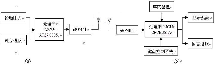
Figure 1 TPMS system composition block diagram
The system adopts the integrated wireless transceiver chip nRF401 from Norway Nordic Company, which works in the 433MHz international ISM frequency band. The dual working frequency band can be freely switched, FSK modulation and demodulation, and direct digital synthesis DSS + phase-locked loop frequency stabilization PLL for frequency synthesis. The frequency stability is good, the anti-interference ability is strong, the receiving sensitivity is up to -105dBm, the maximum transmitting power is +10dBm, and the power consumption is low. When receiving standby state, the current is only 8μA, and the data transmission rate can reach 20kbit/s. The nRF401 uses a commonly used 4 MHz crystal as the PLL frequency reference without the need for expensive varactors. In addition, its demodulator is DC balanced, and the input data allows for various 011 sequences without the need for Manchester encoding. The controller's UART is directly connected to the DIN and DOUT terminals of the nRF401. After the MAX232 level conversion, it can be directly connected to the serial port of the computer. Another very important feature of the nRF401 is that the receiver has a high band impedance, which means no external is required. The surface wave filter eliminates the need to debug components.
The overall hardware structure design is shown in Figure 2 and 3. Due to the use of dedicated sensors, relatively simple hardware circuits can be designed. The power supply is provided by a lithium battery. In the TPMS, since the slave cannot transmit the pressure detected at any time to the host computer through the cable, wireless transmission should be adopted. Because the working environment of the automobile tire is relatively bad, the general wireless transmission module can not realize its function. It has been proved that the wireless transceiver chip nRF401 communication system works reliably and stably in the industrial environment with relatively harsh environment.
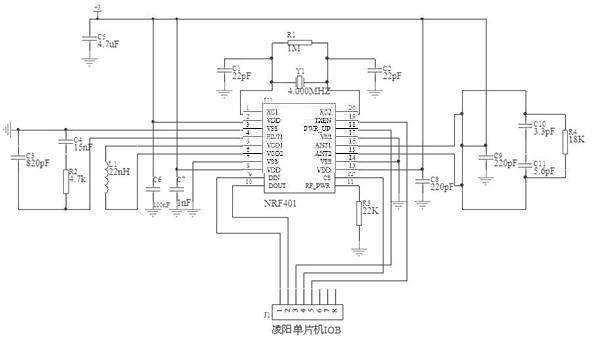
Figure 2 Central monitor transmitter module hardware schematic
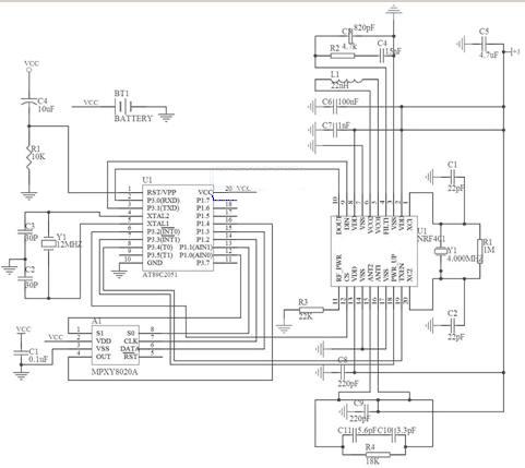
Figure 3 tire detection module hardware schematic
In the hardware circuit design, we fully consider the interference problem of the data received by the system, and adopt a certain anti-interference scheme for the design of relevant parts. For example, in the design of the PCB layout of the transmitting module, high-frequency interference is fully considered. The use of the Sunplus 61 board as the controller of the upper computer utilizes its own advantages of filtering and eliminating interference. The power is directly converted from the 12V power supply in the car through the voltage conversion circuit.
The wireless communication part of the system adopts the master-slave structure. The lower position machine is composed of the monitoring controller installed in the tested vehicle. The main station is the monitoring computer located in the control center; different lower position machines will detect through the wireless communication circuit. The data arrived is sent to the monitoring computer. Only one lower computer can work at the same time. The communication here is actually a shared medium. In order to avoid conflicts between multiple lower computers competing for channels, only the primary station sends an allowable communication signal to a lower computer. Only send data. The communication module consists of nRF401 and few peripheral devices. PCB antenna is used. The data transceiver terminal of nRF401 is directly connected to the serial port of MCU. The MCU controls the state of nRF401 with three I/O ports. The low voltage MCU with 3V power supply is selected. It shares the same power supply and the same 4MHz crystal oscillator as the nRF401.
2 software design
In wireless communication systems, due to factors such as power supply, space noise, and transmission path, direct transmission of data is susceptible to interference. Therefore, it is necessary to design a transmission protocol to ensure reliable establishment on such unreliable physical links. Data connection, the system's wireless communication protocol mainly works in the data link layer of the OSI reference model, through which the necessary error detection coding is performed. Error control ensures correct and reliable data transmission.
The lower computer (four for example) collects data in real time, and the system only has one nRF401 chip receiving, and adopts the working mode of wirelessly transmitting data at the same frequency, so the four lower computers cannot simultaneously send pressure data. It is necessary to use the answer dialogue method to resolve this conflict, that is, each lower computer is assigned a password, which can be regarded as the assigned address, and all the lower computers are usually in the state of accepting data, waiting for the request of the upper computer. When the host computer sends a data request with an address, the lower computer judges whether to respond according to the received address; the upper computer sends the address of each lower computer in sequence and immediately changes to the receiving state, and the data is not received after 5 seconds delay. Then it is changed to the transmission state, and an error is reported which the lower computer has a problem, and the request is sent to the next lower computer; the lower computer receives and judges the address data, and if it is its own address, the password is correct, and immediately becomes the transmission state, and the transmission is performed. The latest data collected, after transmission, changes back to the receiving state, waiting for the host computer to send back the data to confirm that the transmission is correct (because environmental factors may cause transmission errors); the upper computer receives the data and saves it, then becomes the transmitting state, The lower computer sends back the data just received, and then waits for the acknowledgment signal of the lower computer; the lower computer receives the returned data and compares it with the data just sent. If it is consistent, it sends an acknowledgment signal. If it is inconsistent, continue. Send, and repeat the last two steps; if the host computer accepts the confirmation signal, Then the saved data is sent to the handler, and if not, the address request is repeated.
After the power-on reset of the lower computer, the above initialization procedure is started, and the loop in the flow chart is entered. The pressure and temperature acquisition are completed in the timer interrupt, and the interruption time is tentatively scheduled to be collected every 5 seconds. In order to improve the system real-time and anti-interference ability, when the voltage or temperature data collected by the lower computer exceeds the specified range, the lower computer immediately becomes the transmitting state, and a special alarm signal is issued, and at this time, the upper computer does not work at any time. Once the status receives the alarm signal, it immediately interrupts the current communication and establishes communication with this lower computer.
In order to improve the anti-interference ability of the system, the software filtering part is added in the software design, the data collected in the last 5 times in the continuous buffer is stored, and the average value is obtained, and then displayed as the air pressure at that time. This eliminates spikes that occur due to inaccuracies in certain data, causing the system to misjudge.
3 Conclusion
This paper introduces the design of wireless communication data acquisition system in automobile tire pressure monitoring system from two aspects of hardware and software. The circuit structure is simple and anti-interference is strong; the system can collect the temperature and pressure in the tire in time and accurately, and can Alarm when a dangerous situation occurs. The system needs to be improved in terms of energy saving, stability and installation.
The author's innovation point: the use of a variety of anti-interference methods in the software and hardware design process of the car tire pressure monitoring system, greatly improving the system's anti-interference ability.
references
1. Zhang Peiren. Principle and Application of 16-bit Single Chip Microprocessor (Lingyang SPCE061A)[M]. Tsinghua University Press, 2005
2, Wang Xingzhi. AT89 series single-chip principle and interface technology [M]. Beijing University of Aeronautics and Astronautics Press, 2004
3. Li Jinfeng, Cao Shun, Wei Lifeng. Application of wireless transceiver module nRF401 in mines[J]. 2006,2:241-243
4, Yi Yi, Tang Rongjiang, etc. Software anti-interference measures of single-chip application system. Microcomputer information [J]. 2007,5:101-103
5. Li Jie. Factors and Preventive Measures of Early Wear of Automobile Tires[J]. Special Purpose Vehicles, 1998(4)
6. Li Yongming. Interference Analysis and Countermeasures in High Frequency PCB Design[J]. Electronic Technology 2003(1)
Led Ufo High Bay light using Samsung led light source, providing excellent lumen output, long-lasting stability and splendid sight. Fins convection heat radiating design, enlarge heat radiating area, improve heat radiating efficiency and ensure safety. Thickening aluminum cover with high quality surface painting treatment and strong corrosion resistance. PMMA integrated lens enable a wide lighting area and excellent dustproof performance. Intelligent waterproof driver, rated IP65, CE qualified, with overload, undervoltage and convection protection. Led UFO High Bay light are an ideal lighting solutions for outdoor like street, dock, station, construction site etc.
Led UFO High Bay
Led Ufo High Bay,Led High Bay,Ufo Led High Bay,Industrial Led High Bay Light
Guangdong guangzhidian lighting Co., Ltd. , https://www.gzdlighting.com