In addition to traditional lead-acid batteries, modern electric /hybrid vehicles often have a large capacitor (40F or larger) as a backup power source. The capacitor is placed under the rear seat to ensure extra driving for 10 to 15 minutes. During this time the driver will be able to reach the next charging station or gas station.
This article refers to the address: http://
Lead-acid batteries can only be discharged to about 8V, and capacitors can be discharged to 0V. This capability of the capacitor needs to be implemented with a current-sense amplifier that can measure 0V input.
However, most high-side current-sense amplifiers operate with a common-mode input range and a limited supply voltage range. For example, the MAX4081's common-mode input and supply voltage range is 76V to 4.5V. In a bidirectional (charge/discharge) current sense application, when setting the zero load current point (ie, the voltage output corresponds to zero load current, where VSENSE = 0V), an external reference is usually placed at the reference input (REF) (eg +2.5) V). For the MAX4081, the lower 4.5V common-mode limit often makes it unusable for applications that require current sensing close to ground.
The designer can solve this problem by connecting a charge pump to the circuit (Figure 1). The micro charge pump (IC2) has a supply voltage of 5V, which is the same as the current sense amplifier. The output of the charge pump (5V) is used as the negative supply voltage for the "ground (GND)" pin of IC1. The REFA and REFB of IC1 are connected to the "ground" of the circuit.
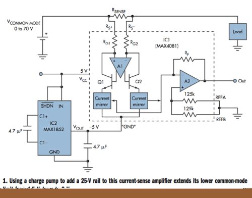
Thus, IC1's internal operational amplifier (A2) operates on a 5V supply rail (10V amplitude) and its non-inverting input (REF pin) is located at 0V between the rails. When VSENSE = 0V, the output voltage is 0V. VSENSE then increases with load current, resulting in 5x, 20x or 60x output depending on the gain suffix F, T or S of the device model. Thus, the effective common mode range is extended to 0V to +70V, while the original technical parameters are unchanged (VOS < 0.6 mV, gain error < 0.6%).
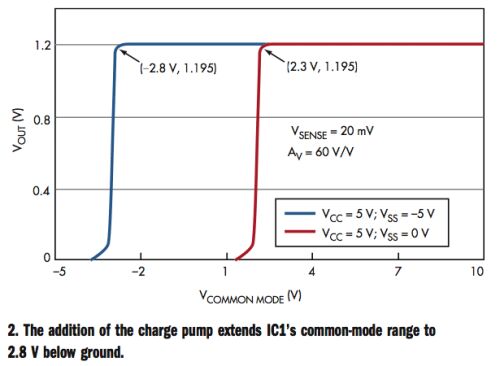
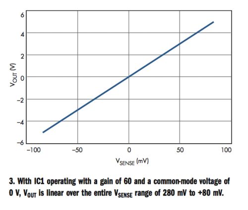
Tests on the circuit of Figure 1 show that the common-mode voltage of the current-sense amplifier (connecting "ground" to 5V) can be reduced to 2.8V (Figure 2). In contrast, the common-mode voltage in standard applications (GND to 0V) can be reduced to +2.3V. However, when REFA and REFB are shorted to GND, the output swings up and down at GND to 5V. Figure 3 shows the output of IC1 with a common-mode voltage of 0V over the entire sense voltage range.
The typical supply current of IC1 (103?A) constitutes a small load current for IC2, preventing overload and voltage drop at its output. Pay special attention to the situation when the output falls below GND. At this time, the load current flows from the GND terminal of IC1 and then flows into the charge pump, and the negative output of the charge pump may drop (toward 0V). One solution is to use a larger capacitor in the charge pump or limit the output voltage of the sense amplifier.
It can be equipped with different type of storage battery such as lead acid battery, Nickel Cadmium Battery, silver zinc battery, Lithium Ion Battery and Other storage batteries, providing various output voltage classes.
Built-in storage battery and charger, equipped with the function of over-charge and over-discharge protection and capacity display. It is used as working power supply for lightings, communications, laptops, and special instruments of emergency working, field working, press interviews, special vehicles and other fields.
48V Dc Power Supply,Universal Power Supply,Power Supply 500W,Electrical Load Power Supply
Xinxiang Taihang Jiaxin Electric Tech Co., Ltd , https://www.agvchargers.com