LED backlighting is becoming a boom and flooding people's lives. From the debut of LED-backlit notebooks in 2008 to the gorgeous debut of LED-backlit LCD TVs in 2009, it has attracted people's attention. For LED backlights of medium and large size displays , several technical problems must be solved. The most direct problem is the consistency of the brightness between LEDs. The number of backlight LEDs required for medium and large size displays is up to tens to thousands. If the brightness of the LEDs is inconsistent, the backlight will be different, which will seriously affect the display.
This article refers to the address: http://
We know that the brightness of an LED is determined by the current flowing through the LED, so the way to ensure that the brightness of the LED is the same is to ensure that the current flowing through all the LEDs is exactly the same. This means that in the case of multiple LED backlights, the series connection method is better than the parallel mode to achieve the uniformity of the illumination brightness. In this case, it is important to control the current accuracy of the LED string to ensure that the brightness of the backlight LED string between the customer's product and the product is consistent.
But the number of LEDs connected in series is unlikely to be too much. At normal illumination, the voltage drop across the white LED is approximately 3.5V, meaning that the voltage drop across 10 phases can be as high as 35V. For the 14" display, the number of LEDs required is more than 40. If all are connected in series, the voltage drop will reach about 140V or higher, not to mention the larger display. So, centering, In the case of large-size displays, the way of full series connection is unrealistic and must be combined in series and parallel. When the system drives the backlight LED string in this way, it is not always possible to achieve accuracy requirements for each current. To ensure the backlight effect, ±1% current accuracy means that the maximum difference between the two channels can reach 2%. Unless the current accuracy index is exceptionally high, it is necessary to limit the current difference between the paths. The current matching degree is usually used to indicate the maximum difference level between multiple parallel outputs on the same system, which is defined as follows:
Imatch = (Imax-Imin)/Iavg*100%
That is, the difference between the maximum value and the minimum value of each current and the percentage of each path average.
Because the LED backlight of the medium and large size display has the above basic requirements, a special LED driver chip is needed to help the system realize the driving management of the backlight LED, simplify the system design, and provide more control and protection functions. The latest PT4112 from China Resources Converse Technology is such a product.
PT4112 technical features
The PT4112 is a 6-channel white LED driver IC with up to 10 white LEDs in series, so a single chip can drive up to 60 white LEDs. The PT4112 not only has excellent current accuracy and current matching, ideal conversion efficiency, and wide operating voltage range, but also integrates rich control functions and comprehensive protection functions. The main functions and technical features of the PT4112 are as follows:
1. Ultra high precision. Using patented design technology and advanced analog process technology, PT4112's current accuracy is up to ±2%, and the current matching between 6 channels can be as high as ±1.5%, which is not only second to none in local original products, but also fully meets High-end notebooks require such high image quality applications.
2. High conversion efficiency. Through patented design techniques and advanced analog process processes, the conversion efficiency of the PT4112 can be as high as over 90%.
3. Wide operating voltage range. The 5 to 25V operating voltage range allows engineers to choose the PT4112 in more applications without worrying about the operating voltage.
4. Support PWM brightness dimming, PWM signal duty cycle range is 0 ~ 100%. Input the PWM signal to the BRT port of the PT4112 to directly control the LED light on and off. By maintaining the state of the circuit during dimming off, the AC ripple on the output capacitor can be kept small over a large duty cycle of the PWM to reduce potential audible noise.
5. Various protection functions are complete. The PT4112 features open-circuit over-voltage protection, current-by-switch cycle current limiting, output shutdown protection, overtemperature protection, input voltage undervoltage lockout, and soft-start. In addition, the PT4112 has a unique FAULT protection function. By supplying a driving signal to the external PFET, it is only necessary to connect this PFET between the input and the inductor. When a serious error occurs in the system, the PFET can supply power. Portable applications, usually lithium battery packs, are isolated from the WLED to prevent damage to the battery due to leakage of large currents, making the entire system safe and reliable.
6. Unique open circuit automatic brightness compensation function. This is an ingenious design of the PT4112, an optional feature that is set via the IFB port of the PT4112. When the IFB port is left floating, if one of the 6 outputs stops working, the remaining 5 currents are automatically increased by 20%. Grounding the IFB port turns off this feature.
7. Good EMI characteristics. The EMI of the PT4112 is effectively suppressed by using special design techniques.
Typical application circuit design and precautions
The PT4112 application circuit design method is as follows:
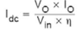
Current setting
The output of the 6 current paths, the maximum current of each channel can reach 25mA. The output current can be set by R1 externally connected to the Iset port. Select the different R1 resistor values ​​to get the required output current:

Where R1 is the set resistance, the unit is taken as KΩ, and Iset is the required current, and the unit is taken as mA. The corresponding resistance of 20mA is 62KΩ.
2. Selection of inductance
The choice of inductors will be an important factor in determining the stability of the entire system. There are three main characteristics of the inductor: sense, DCR and saturation current. The recommended range of inductance for PT4112 is 4.7-10μH, which is recommended if the size and package allow. Use a 10μH inductor because such a choice system can achieve higher efficiency and less ripple. In addition, the 10μH inductor also helps to obtain a large output current when the output current limit is constant. In the boost circuit, the calculation of the inductance is usually calculated according to the following formula:
The peak-to-peak value of the inductor current ripple can be calculated as follows:
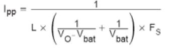
Thus, the peak value of the inductor current is: 
In order to ensure stable operation of the system, the saturation current should normally be 1.5 times the peak current.
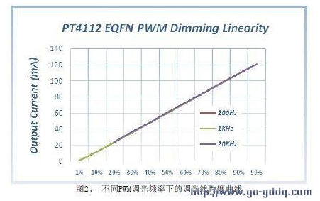
3. PWM dimming PWM dimming can be achieved by applying a PWM chip to the BRT port of the PT4112. PWM dimming is effective for all channels simultaneously. The PT4112 does not support PWM dimming for a single channel. The frequency of the PWM signal is suitable in the range of 100 Hz to 1 kHz, as shown in Figure 2.


4. PCB layout considerations PCB layout is a very important part for high frequency and high current power supply systems, so the following points should be followed:
1) The Iset terminal resistance should be as close as possible to the chip to effectively reduce the influence of noise on the current setting;
2) The input capacitor Cin and the output capacitor Cout should be as close as possible to the chip to ensure stable operation of the system.
3) Input to the SW terminal, and the current from the SW terminal to the output will have a maximum current of 3 amps, so the trace current needs to ensure the corresponding current density.
Our company offers rubber, and specialty seal and o-ring for molding electronic and electrical Connectors, both circular and rectangular types. We have in house capabilities and quick turn around.
Cable Grommets with various Grommet Shapes, Rib Styles, Slot Shapes, Inner Flanges, and Colors - To have access to our 3D Cable Grommet Design Tool
Silicone Rubber Products,Cable Silicone O-Ring,Rubber Seal,Custom Silicone Seal,Waterproofing O-Ring,Tpe Grommet
ETOP WIREHARNESS LIMITED , http://www.etopwireharness.com