This article mainly introduces the design of power supply filter, revealing all aspects in the process of designing power supply filter for you.
Power filterThe power filter is a filter circuit composed of capacitors, inductors and resistors, also known as "power EMI filter" or "EMI power filter", a passive two-way network, one end of which is the power supply and the other end is the load . The principle of the power filter is one kind-impedance adaptation network: the greater the impedance adaptation between the input and output sides of the power filter and the power and load sides, the more effective the attenuation of electromagnetic interference. The filter can effectively filter out the frequency point of a specific frequency in the power line or the frequency other than the frequency point to obtain a power signal of a specific frequency, or eliminate a power signal of a specific frequency.
Working principle of power filterThe power filter is an electrical equipment that effectively filters out the frequency point of a specific frequency in the power line or the frequency other than the frequency point. The function of the power filter is to obtain a power signal of a specific frequency by connecting the power filter to the power line, or to eliminate the power signal of a specific frequency.
Using this characteristic of the power supply filter, a square wave group or compound noise after passing the power supply filter can be turned into a sine wave of a specific frequency.
High-power power filters such as Satons, UBS, inverters, etc. will generate a large amount of harmonic currents. This type of filter requires active power filter APF. APF can filter out the 2~50th harmonic current.
Power filter structurePower filters are generally designed as passive filters consisting of resistors, capacitors, and inductors, without active components such as transistors. The picture on the right is an example of a power supply filter. The top of the power supply filter is connected to the power supply. There is a common mode inductor at the power supply end, that is, the two wires of the power supply are wound on the core in the same direction. If there is a common mode signal on the power supply line, The magnetic fields generated by the common mode inductors will add up, so there is a larger impedance, and the magnetic fields generated by the common mode inductors for the differential mode signals will cancel each other, so the common mode inductors can flow. The current flowing through the power supply is mainly in the differential mode, but the noise may also appear in the form of differential mode. To suppress the differential mode noise, you need to use a differential mode inductor or have a separate inductor for each phase.
Special safety decoupling capacitors are used on the power filter, which are divided into two types: X capacitors and Y capacitors:
X capacitor: suppress differential mode interference (interference between power lines).
Y capacitor: Suppress common mode interference (interference between each group of power lines and the ground).
Since the increase in Y capacitance will increase the leakage current of the electrical appliance, and the leakage current of the electrical appliance has its specified range, the Y capacitance cannot be too large, and it will generally be smaller than the X capacitance.
X capacitor and Y capacitor are safety capacitors, that is, they will not cause electric shock after failure, and will not affect personal safety. Both have a self-healing effect, which will restore the original insulation state of the partially short-circuited part.
Power supply filter designThis article combines the practice of research and design of power supply filters, while simplifying the design process of power supply filters, it can still meet the needs of practical applications.
Analysis of Magnetic Flux in Common Mode Choke Coil in Power Filter
The role of the common mode choke in the power filter is generally described as follows: "The magnetic fields on both sides of the common mode choke die cancel each other, so there is no magnetic flux to saturate the die." Although this argument concretizes the intuitive description of the role of common-mode chokes, the essence is not the case. Because according to Maxwell's equation in electromagnetic field theory, the following results can be obtained:
Assuming that the current density J produces a magnetic field H, another nearby current will not cancel or prevent the magnetic field or the resulting electric field; similarly an adjacent current can cause a change in the path of the magnetic field;
In the special case of toroidal common mode inductors, the differential mode current density in each lead can be assumed to be equal and opposite in direction. The resulting magnetic field must have zero sum on the periphery of the toroidal core, but not zero on the outside.
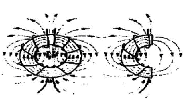
The function of the magnetic core is like the effect it exhibits when it splits in half at the gap of the coil winding. Each winding generates a magnetic field in half the area of ​​the toroidal coil, which means that the magnetic field passing through the air must form a self-closed loop. Figure 1 is a schematic diagram of a toroidal core and a differential-mode current magnetic circuit. In order to obtain the common mode inductance and minimize the differential mode inductance, it is best to use a magnetic core with a larger cross-sectional area to make a multi-turn coil. Using a larger spiral tube core (not necessarily using such a core) can incorporate effective differential mode inductance in the common mode choke. Because the differential mode magnetic flux is far away from the magnetic core (ring structure), it may produce extremely strong radiation, especially when the filter is mounted on a printed circuit board (PCB), this radiation can be coupled to the power line, making the conduction Launch enhancement. When the magnetic material is brought into the field (for example, the toroidal core is placed in the iron case), the differential mode permeability will increase significantly, and the core will be saturated due to the differential mode current.
In order to achieve an effective filter design, the radiation problem caused by the magnetic flux leaving the core must be solved. There are two specific solutions: either confine the differential mode magnetic flux to the magnetic structure object (pot-shaped iron core), or provide a high permeability path for the differential mode magnetic flux (E-shaped iron core). Selection of power filter design parameters
Since the power filter is connected to the main power line, in addition to the mismatch of source impedance and load impedance, the strict restrictions on the inductance of the series inductor and the capacitance of the parallel capacitor must also be considered in the design. The series sensor used in the filter is limited by the allowable voltage drop at the power frequency and cannot be selected too large; the parallel filter capacitor is limited by the allowable ground leakage current, and cannot be selected too large. Due to the above limitations, it is often difficult to meet the requirements for filter insertion loss at the same time. Maximum allowable series inductance of power supply EMI filter
Suppose the inductance of the series inductor in the filter is L, the equivalent resistance is R, the grid frequency is ωm, and the grid-side rated operating current is Im. At the grid frequency, the voltage drop across the inductor is:
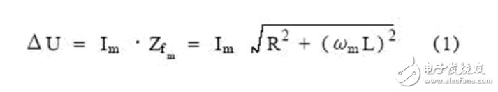
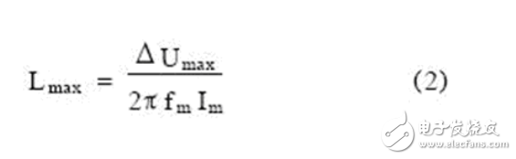
Taking into account the influence of the surge current that may be generated in the power grid, ΔU is usually limited to less than 10% of the rated working voltage. If the voltage drop on R is ignored, and the allowable voltage drop on the inductor is ΔUmax, the maximum allowable series inductance value is:
Maximum filter capacitance allowed by power supply EMI filter
The filter capacitor in the power EMI filter is usually connected between the phase line and the earth. If the capacitance of the capacitor is too large, it will cause excessive leakage current, thereby endangering personal safety. Its leakage current value is:
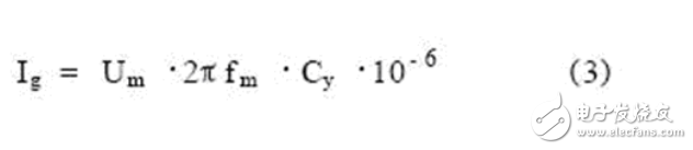
From equation (3), the filter capacitor allowed in the power supply EMI filter can be obtained as:
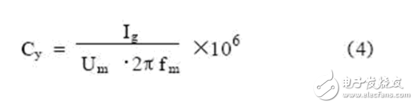
Where: Um is the grid voltage, V; fm is the grid frequency, Hz; Ig is the allowable ground leakage current, mA.
Based on the above analysis, to limit the maximum value of the series inductance and parallel capacitance in the power filter, the maximum value of the LC product can be obtained as:
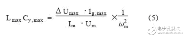
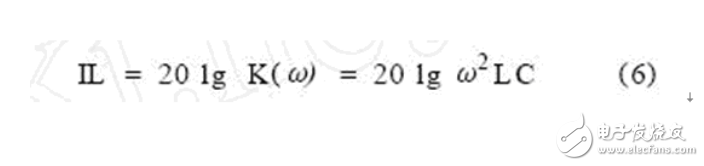
For low-power electronic devices, the value of LmaxCy,max is usually 100μHμF, which is a very small value. Taking a single-stage LC filter as an example, in order to simplify the analysis, the insertion loss is replaced by voltage attenuation, and the insertion loss at this time can be obtained as:
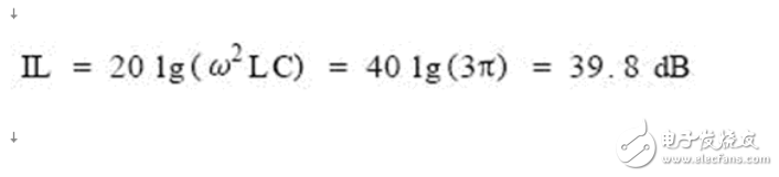
If the LmaxCymax value is 100μHμF and the frequency is 150kHz, the insertion loss is:
Installation of power filter
The installation quality of the power filter has a great influence on the attenuation characteristics. Only when the filter is correctly installed on the equipment can the expected attenuation characteristics be obtained.
The installation of the filter should follow the following principles:
(1) The power supply filter of the power supply line should be installed at the power inlet of the equipment or shielding case, and the filter should be shielded, and the shielding body should be well connected to the equipment case;
(2) For transportation vehicles such as urban rail transit, electric motors and various electrical switchgears and other interference sources should be installed in the same shielded box as the power filter. The filter is installed at the power inlet, and the power input line should not be exposed in the box. ï¼›
(3) The capacitor lead in the filter should be as short as possible to avoid resonance between inductive reactance and capacitive reactance at lower frequencies, and the capacitor should be installed orthogonally to other components to reduce mutual coupling;
(4) There is a large short-circuit current passing through the grounding wire of the filter, which will cause harmful electromagnetic radiation. Therefore, the filter suppression component itself must be well electromagnetic shielded and grounded;
5) The input and output leads of the filter cannot cross, and there should be a shielding layer between the input leads and the output leads, otherwise the filter characteristics of the filter will be reduced.
ConclusionBoth common mode magnetic flux and differential mode magnetic flux exist in the common mode choke of the power filter. In order to obtain common mode inductance while minimizing differential mode inductance, it is best to use a magnetic core with a larger cross-sectional area to form a multi-turn coil during the design. In addition, the radiation problem caused by the magnetic flux leaving the magnetic core must be solved.
In the design of the power filter, in addition to considering the source impedance and load impedance mismatch factors, it must also consider its strict restrictions on the inductance of the series inductor and the capacitance of the parallel capacitor to meet the requirements for the insertion loss of the filter. .
This is the end of the related design of the power supply filter. I hope this article can be helpful to you.
4000 - 5000 Puffs (included)
Shenzhen Zpal Technology Co.,Ltd , https://www.zpalvapes.com