Recently, the famous Max sent me an email asking if I know that PCB design tools can allow objects—like LEDs or other components—to be placed in a radial manner.
This is a very good question. If you stop and think about it, PCB designers have been using the concept of grid for decades, and we tend to like clean and tidy rows and columns. Maybe because we like matrices and linear algebra. I don't know, but for whatever reason, when you're designing a circular PCB (including placement of components and routing problems), the idea of ​​a linear grid is limited!
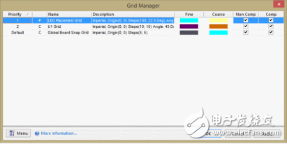
I really don't know if there is a PCB design tool that can do this - I haven't seen it yet - but I know that AlTIum Designer allows for radial meshes. In fact, to place components or other objects, users can set up multiple different grids and have them overlap and work.
When the advanced grid feature was added to AlTIum Designer version 10, I made an interesting little project. This is the PCB of a stroboscopic guitar tuner.
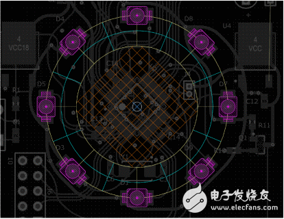
I want to install an ARM7 microcontroller in the 45 degree direction of the center of the board, so I used the center of the board as the origin, adding a rectangular grid that can be rotated 45°. In other words, the rectangular mesh does not have to be parallel to the XY axis.
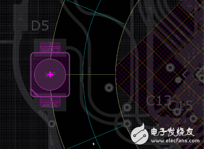
Outside of this thing you can see the polar grid I used for the LEDs. This allows me to place LEDs in completely separated circles.
The grid is configured with a priority order, with the default alignment grid at the center behind the slanted grid, which itself is placed behind the polar grid in order to place the LEDs.
Essentially it means -- when I place the part -- the mouse cursor snaps to any mesh that is hovering over it. As a result, making such a design becomes faster and easier.
If you think about it, we are so accustomed to using the word "grid" and accustomed to using it as a "North-South thing." I grew up doing math in the "Grid" book, and when I first started learning electronics, hand-drawing using grid paper would be cleaner. However, in the case of modern tools, it is not a real mesh. Instead, what we really do is control where the mouse cursor is captured. Can you imagine that the tracks on the PCB really need to stay on the grid? This is untenable!
So, in essence, I think we'd better call this feature "capture management." But no matter what we call it, it really helps us to put these glowing LEDs in a perfect circle! This is the 3D view of this board I made:
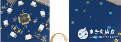
I chose the LED light to be the blue OSRAM TOPLED series reverse gull-wing type. The idea is that the LED is designed to let light pass through the back of the PCB, where there is a plexiglass panel. Cool! Maybe Max wants to use this method on the dial of his Inamorata PrognosTIcaTIon engine!
- This article was translated from EE Times.
Translator: Iris Zhang, Editor of Electronic Enthusiasts
Zoom Camera , Thermal Camera ,Drone searching Light, Drone Mega Phone,Drone Survey Gimbals
Zoom Camera, Thermal Camera,Drone searching Light, Drone Mega Phone,Drone Survey Gimbals
shenzhen GC Electronics Co.,Ltd. , https://www.jmrdrone.com