I. Project Overview
1.1 Introduction
The ordinary alarm clock only has the time display and voice reminder function. If an alarm clock is envisaged, not only can the time display be displayed, but also the relevant transaction reminder can be displayed on the dial when the set alarm time is reached, then the function of the alarm clock can be greatly improved. rich.
1.2 Project Background / Motivation
First, with reference to the effects demonstrated by the PSoC Rocks routine, it is extended to use a series of LED lights for text display;
Secondly, I have seen someone using a motor to drive a series of LED lights and applying certain controls to complete the display of the dial clock. It is both interesting and enjoyable, so I would like to complicate its function and try to complete the text display. ;
Third, considering that the PSoC development board integrates a gravity sensor, it can be used to extend the function of the alarm clock, and display different contents when the device is in different placement states;
Second, the demand analysis
2.1 Functional requirements
1. Clock display function: This is the most basic function of the system. The controller controls the lighting and extinction of the LED light. Under the human visual persistence effect, the dial and the walking pointer appear in the line of sight; Ordinary clocks are more entertaining and interesting.
2, temperature display function: This is an additional function of the clock system, mainly to expand the clock function and further utilize the resources of the PSoC chip.
3, alarm clock function: This is the larger highlight of the system, the alarm of the alarm and the text reminder, to complete the reminder function from a better and more accurate.
2.2 Performance requirements
1, the accuracy of the clock requirements: This is one of the performance that the clock must have, the inaccurate clock is basically useless.
2. Temperature accuracy requirements: Temperature detection allows for certain errors. Since high-precision measurement is not involved, errors within 1~2 degrees are acceptable.
3, the clarity requirements of the display system: the visual effect of the LED display system should be clear enough to be easily identifiable.
Third, the program design
3.1 System function realization principle (except for pictures, there is a text introduction)
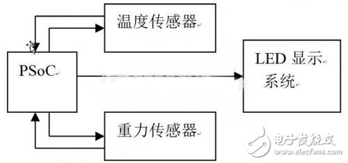
System hardware block diagram
System function description: The system drives a series of LED lights through the motor, combined with the human visual persistence effect to complete a simple display system. The gravity sensing sensor is used to detect the alarm state and feedback to the controller to control the LED display system to display the content in different modes (clock mode, temperature mode, setting mode); the temperature sensor is only enabled in the temperature mode for detecting The ambient temperature is then displayed by the LED display system; in the clock mode, under the action of the controller, the blinking of each LED light is controlled to realize the display of the dial clock.
3.2 Hardware platform selection and resource configuration
The hardware platform uses a self-made platform based on PSoC. Because of the implementation principle of the system function, the development board provided by the contest cannot be used, and the modules integrated by the development board are not all used, so we choose to design the hardware structure independently. Simply put, the hardware mainly includes PSoC chip, acceleration sensor, temperature sensor and dozens of LED lights plus a DC motor (requires a reducer). The hardware structure uses a long strip structure that is easy to make rotary motion, as shown below. Shown.
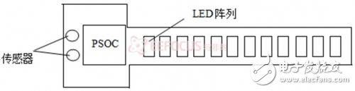
Simple hardware structure diagram
3.3 system software architecture
The components of the construction system mainly include detection components, controllers and display components. The system architecture built by these components can be briefly explained by the following figure.
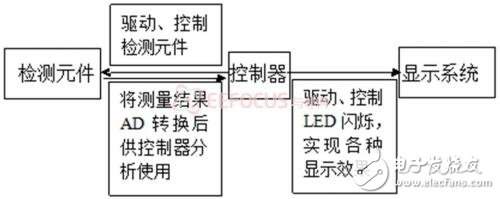
System software architecture
Since the built system is not complicated, its architecture is relatively simple and straightforward. The following is a brief introduction of each module. Detection component: equivalent to a signal acquisition component, responsible for collecting information about the surrounding environment and feeding back to the controller for analysis, and then the controller issues corresponding commands to control other components. The key to the signal acquisition phase is the processing of the acquired signals, such as AD conversion. The Delta-Sigma ADC integrated by PSoC is fully capable of meeting our high-precision signal acquisition requirements.
Controller: It is the core part of the system. All the functions of the peripheral device are basically commanded and controlled by the controller. The key to the function of the system is that the controller can correctly control the flashing of the LED light to complete the display.
Display system: It consists of a motor and a series of LED lights. The realization of the display function mainly depends on the control command of the controller and the rotation of the motor.
3.4 System software flow (except for pictures, there is a text introduction)
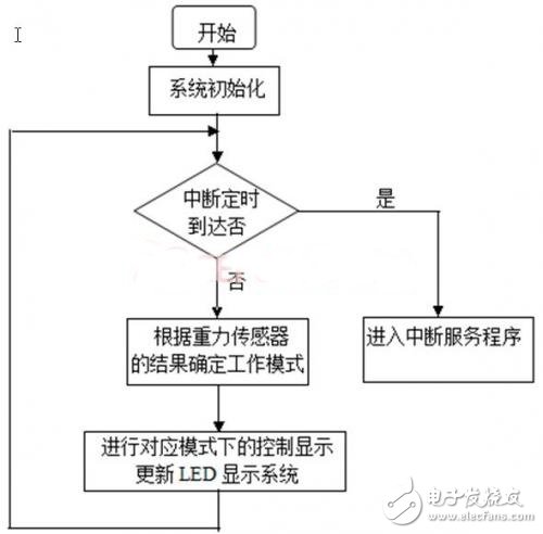
Main program flow chart
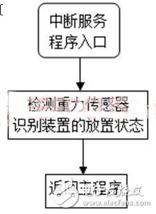
Interrupt service program flow chart
3.5 System Expected Results
In the clock mode, the LED display system displays the dial-type clock, that is, the clock with the rotating hour hand, minute hand, and second hand. When the set alarm time is reached, the sound is emitted at 7:00 in the morning and the dial displays “get upâ€, prompting to get up; afternoon At 1 o'clock, the sound on the dial shows “rest†to remind the lunch break, etc.; the alarm is rotated 90 degrees to enter the temperature display mode, and the temperature of the environment is displayed according to the measured value of the temperature sensor; continue to rotate the alarm 90 degrees into the setting mode, which can be used Set the alarm time.
Surface Treatment DC Power Supply
Electrolysis Dc Power Supply,Charging Dc Power Supply,Motor Test Dc Power Supply,Experiment Dc Power Supply
Yangzhou IdealTek Electronics Co., Ltd. , https://www.idealtekpower.com