I. Introduction
The basic working principle of PWM switching regulator or steady current power supply is that under the condition of input voltage change, internal parameter change and external load change, the control circuit performs closed-loop feedback through the difference between the control signal and the reference signal to adjust the main circuit switching device. The pulse width is turned on so that the output voltage or current of the switching power supply is stabilized by the control signal. The switching frequency of the PWM is generally constant, and the control sampling signals are: output voltage, input voltage, output current, output inductor voltage, and peak current of the switching device. These signals can form a single-loop, double-loop or multi-loop feedback system to achieve the purpose of voltage regulation, steady current and constant power. At the same time, some additional functions such as overcurrent protection, anti-biasing and current sharing can be realized. For the fixed-frequency widened PWM closed-loop feedback control system, there are mainly five PWM feedback control modes. The following is a steady-state step-down chopper composed of VDMOS switching devices. The development process, basic working principle, detailed circuit schematic diagram, waveform, characteristics and application points of the five PWM feedback control modes are illustrated to facilitate the application. And simulation modeling research.
Second, five kinds of feedback control mode of switching power supply PWM
1. Voltage Mode Control PWM (VOLTAGE-MODE CONTROL PWM):
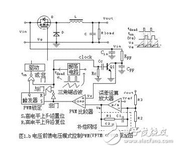
Figure 1 shows the schematic diagram of the voltage mode control PWM feedback system of the BUCK step-down chopper. Voltage mode control PWM is the first control method used in the early 1960s when switching power supplies were just beginning to develop. This method, combined with some necessary overcurrent protection circuits, is still widely used in the industry today. The voltage mode control has only one voltage feedback closed loop, and the pulse width modulation method is adopted, that is, the slowly varying DC signal sampled and amplified by the voltage error amplifier is compared with the ramp wave of the constant frequency triangular wave, and the pulse width is obtained by the pulse width modulation principle. See the waveform in Figure 1A. The pulse-by-pulse current limiting protection circuit must be additionally added. The main disadvantage is the slow transient response. When the input voltage suddenly becomes small or the load impedance suddenly becomes small, because of the large output capacitor C and the inductance L phase shift delay, the output voltage becomes smaller and the delay is delayed, and the output voltage becomes smaller. The error amplifier's compensation circuit delays lag before it can be passed to the PWM comparator to broaden the pulse width. These two delay hysteresis are the main reasons for the slow transient response.
Figure 1A voltage error operational amplifier (E / A) has three functions: 1 to amplify and feedback the difference between the output voltage and the given voltage to ensure the stability of the steady state. The DC amplification gain of the op amp is theoretically infinite, which is actually the open-loop amplification gain of the op amp. 2 Converting the DC voltage signal with the wider band switching noise component at the output of the main circuit of the switching power supply into a relatively "clean" DC feedback control signal (VE) having a certain amplitude. That is, the DC low frequency component is retained and the AC high frequency component is attenuated. Because the frequency of the switching noise is high, the amplitude is large, and the high-frequency switching noise attenuation is not enough, the steady-state feedback is unstable; if the high-frequency switching noise attenuation is too large, the dynamic response is slow. Although contradictory, the basic design principle for voltage error op amps is still "high frequency gain and low frequency gain". 3 Correct the entire closed-loop system to make the closed-loop system work stably.
Advantages of voltage mode control: 1PWM triangle wave amplitude is large, and pulse width adjustment has better anti-noise margin. 2 Duty cycle adjustment is not limited. 3 For multi-output power supplies, the interaction adjustment effect between them is better. 4 Single feedback voltage closed-loop design and debugging is relatively easy. 5 has a good response to the change in output load. Disadvantages: 1 The dynamic response to changes in the input voltage is slow. 2 Compensation network design is inherently more complex, and the closed-loop gain varies with input voltage to make it more complicated. The 3 output LC filter adds a double pole to the control loop. When compensating the design error amplifier, it is necessary to attenuate the main pole low frequency or add a zero point to compensate. 4 It is more complicated and complicated in sensing and controlling the saturation state of the core.
There are two ways to improve the speed response mode of the voltage mode control: First, increase the bandwidth of the voltage error amplifier to ensure a certain high frequency gain. However, this is more susceptible to high-frequency switching noise interference, and measures must be taken on the main circuit and the feedback control circuit for suppression or in-phase attenuation smoothing. Another method is to use the voltage feedforward mode to control the PWM technique, as shown in Figure 1B. A triangular wave with a variable upper ramp generated by charging the resistors and capacitors (RFF, CFF) with an input voltage replaces the fixed triangular wave generated by the oscillator in the conventional voltage mode control PWM. Because the change of the input voltage can be reflected immediately in the change of the pulse width, the transient response speed caused by the change of the input voltage is obviously improved. The feedforward control of the input voltage is open loop control in order to increase the dynamic response speed to changes in the input voltage. The control of the output voltage is closed loop control. Thus, this is a dual loop control system with open loop and closed loop.
2. Peak current mode control PWM (PEAK CURRENT-MODE CONTROL PWM):
The peak current mode control is referred to as current mode control. Its concept was derived from the single-ended self-excited flyback switching power supply with primary current protection in the late 1960s. In the late 1970s, academic research was carried out in depth. Until the early 1980s, the emergence of the first batch of current mode control PWM integrated circuits enabled current mode control to be rapidly applied. Mainly used for single-ended and push-pull circuits. In recent years, current mode control faces the challenge of improving voltage mode control after performance due to the difficulty in achieving synchronous noise-free slope compensation technology and the poor anti-noise performance required for large duty cycles. Because this improved performance voltage mode control is equipped with input voltage feedforward function, and has perfect multi-current protection and other functions, it has the advantages of most current mode control in the control function, but it is not difficult to implement. More mature.
As shown in FIG. 2, the error voltage signal VE obtained by the difference between the output voltage VOUT and the reference signal VREF after being amplified by the operational amplifier (E/A) is sent to the PWM comparator, and is not generated by the oscillation circuit like the voltage mode. The fixed triangular wave voltage ramp is compared with a triangular waveform or a trapezoidal pointed composite waveform signal VΣ whose peak value represents the peak value of the output inductor current, and then the PWM pulse turn-off timing is obtained. Therefore, the (peak) current mode control does not directly control the PWM pulse width with the voltage error signal, but directly controls the magnitude of the inductor current on the peak output side, and then indirectly controls the PWM pulse width. Current mode control is a control method that has a fixed clock turn-on and peak current turn-off. Because the peak inductor current is easy to sense, it is logically consistent with the change in average inductor current magnitude. However, the magnitude of the peak inductor current cannot be in one-to-one correspondence with the average inductor current, because the same peak inductor current can correspond to different average inductor currents with different duty cycles. The average inductor current is the only factor that determines the output voltage. It can be proved mathematically that by adding at least half of the slope of the slope of the inductor current to the upper ramp of the actual detected current, the disturbance of different average duty currents can be removed, so that the peak inductance is controlled. The current finally converges to the average inductor current. Therefore, the composite waveform signal VΣ has a combination of a slope compensation signal and an actual inductor current signal. When the slope of the applied compensation ramp signal is increased to a certain extent, the peak current mode control is converted to voltage mode control. Because the slope compensation signal is completely replaced by the triangular wave of the oscillating circuit, it becomes the voltage mode control, but the current signal at this time can be regarded as a current feedforward signal, as shown in FIG. When the output current decreases, the peak current mode control tends to change to voltage mode control in principle.
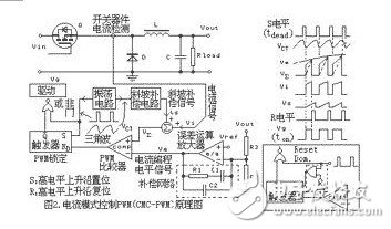
When in the no-load state, the output current is zero and the slope compensation signal amplitude is relatively large, the peak current mode control actually becomes the voltage mode control. The peak current mode control PWM is a double closed loop control system, and the voltage outer loop controls the current inner loop. The inner current loop is instantaneous and fast, and operates on a pulse-by-pulse basis.
The power stage is a current source controlled by a current inner loop, and the voltage outer loop controls the current stage current source. In the double loop control, the current inner loop is only responsible for the dynamic change of the output inductor, so the voltage outer loop only needs to control the output capacitor, and does not need to control the LC tank circuit. Because of this, the peak current mode control PWM has a much larger bandwidth than the voltage mode control. The advantage of peak current mode control PWM is that the transient transient response is fast, and the transient response to changes in input voltage and output load is fast. 2 control loop easy to design 3 input voltage adjustment can be compared with voltage mode control input voltage feedforward technology 4 simple automatic flux balance function 5 instantaneous peak current limit function, inherent inherent pulse-by-pulse current limit function. 6 automatic current sharing parallel function. The disadvantage is that the open-loop instability of 1 duty cycle is greater than 50%, and there is an error of peak current and average current that are difficult to correct. 2 Closed loop response is not as ideal as average current mode control. 3 Subharmonic oscillation is likely to occur, and even if the duty ratio is less than 50%, there is a possibility that high-frequency harmonic oscillation occurs. Therefore, slope compensation is required. 4 is sensitive to noise and poor in noise resistance. Because the inductor is in a continuous storage current state, compared with the current level determined by the control voltage programming, the upper ramp of the current signal of the switching device is usually small, and the small noise on the current signal easily changes the switching device. At the moment of interruption, the system enters the subharmonic oscillation. 5 circuit topology is limited. The interaction adjustment performance of 6 pairs of multi-output power supplies is not good. The main application obstacles of peak current mode control PWM are easy oscillation and poor noise resistance. Oscillation can be derived from current spikes caused by reverse recovery when the device is turned on, noise interference, and insufficient amplitude compensation for ramp compensation. The switching power supply controlled by the peak current mode is apt to oscillate when the power is turned on and the voltage or load suddenly changes greatly.
Steel Light Pole, Steel Street Light Poles, Stainless Steel Light Poles
YIXING FUTAO METAL STRUCTURAL UNIT CO.,LTD( YIXING HONGSHENGYUAN ELECTRIC POWER FACILITIES CO.,LTD.) , https://www.chinasteelpole.com