In the operating environment of today's electronic products, there are countless sources of electromagnetic interference (EMI) and radio frequency interference (RFI), which is due to the increasing use of RF technology. These types of interference cause applications that use differential interfaces to require common mode filtering. While the industry is hoping to use differential signaling to minimize the impact of EMI/RFI, it does not completely eliminate these effects. Differential signals can be subject to external noise and are not recognized by the receiver. Furthermore, in the case where the noise has been coupled to the electronic circuitry in the electronic product, other circuitry that does not integrate differential signaling may be affected and cause more problems.
This article refers to the address: http://
High-speed Universal Serial Bus (USB) 2.0 is one of the most popular differential data interfaces, so this paper aims to demonstrate the need and advantages of using common-mode filters to suppress RMI/RFI noise in high-speed USB 2.0 applications. How to protect the interface from electrostatic discharge (ESD). Common sources of interference include ESD, lightning, switching power supplies (such as DC-DC converters), and wireless devices such as mobile phones, wireless routers, video game consoles, and small notebooks. The most common source comes from devices operating at frequencies between 800 MHz and 3 GHz, but as technology expands, the lower limit of these frequency limits is reduced to 700 MHz and the upper limit is raised to 6 GHz. All of these sources can cause a lot of environmental interference, not only damage each other, but also damage the operation of other equipment. This article focuses on USB 2.0 for portable devices such as mobile phones, and how EMI/RFI interference can cause signal integrity problems if there is no proper filtering.
USB 2.0: Common Mode Filter Requirements
In the Hi-Speed ​​USB 2.0 interface, data is differentially transmitted over two cables at up to 480 Mbps. In order to understand the filtering requirements of this signal, we must first understand the properties of the signal. The signal is a differential signal, indicating that the signal is not grounded, but the two signals are referenced to each other. The data is transmitted through two lines, each of which has a phase that is exactly 180° out of the other. These two lines are usually labeled D+ and D-, indicating the phase properties of the signal. This means that a suitable filter topology must be used to properly filter out any unwanted signals without reducing the signal integrity of the desired differential signal.
In USB 2.0 applications, the single-ended filter topology is not sufficient and designers must use differential topologies such as common mode chokes. This type of filter allows the required differential data to pass without affecting signal integrity while filtering out common mode signals generated by EMI and RFI. The inductive nature of the common-mode filter creates a wide passband of up to 3 GHz or 4 GHz for differential signals, while also producing a narrow passband of less than 100 MHz for common-mode signals.
Second, it is necessary to understand the necessary passbands required for the signal to pass through well. For a 480 Mbps signal, the maximum base frequency that can be generated comes from transmitting "1" and "0" (ie, 1-0-1-0-1-0...) in an alternating manner, producing a frequency of 240 MHz. Since the signal itself is in the form of a square wave, the Fourier series approximation method (Fourier series approximatiON) can be roughly used to multiply the fundamental frequency by a factor of three to obtain the necessary bandwidth for the signal to pass, and the minimum necessary for the differential signal of 720 MHz can be obtained. bandwidth.
Finally, the amount of attenuation required to adequately eliminate unwanted common mode signals must be determined. The amount of attenuation depends on the application. In general, the more the attenuation, the better.
USB 2.0: Signal Integrity Requirements
In order to understand the signal bandwidth requirements, a measure of signal integrity should be defined. The general approach is to measure the eye diagram of the signal and determine the quality of the received signal. The eye diagram shows that the signal transitions between states, indicating how well the receiver can interpret the data being transmitted. High-speed data transmission schemes have a specific mask or template that the signal must conform to in the eye diagram. A typical Hi-Speed ​​USB 2.0 eye diagram (with mask template) is shown in Figure 1.
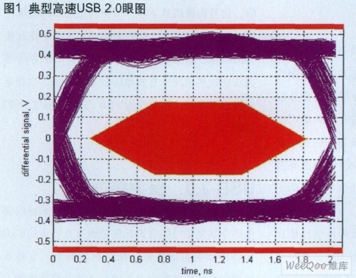
Figure 1 Typical Hi-Speed ​​USB 2.0 Eye Diagram
The USB 2.0 receiver can easily receive the signal shown in Figure 1. As shown, the signal is completely within the eye mask. Let us now imagine the introduction of a common mode noise signal. For example, a small amount of common mode noise with a frequency of 900 MHz and a peak amplitude of 75 mV is introduced. This frequency was chosen to simulate the noise caused by typical mobile phone operation. When common mode noise is introduced as shown in Fig. 2, the quality of the eye pattern is greatly reduced.
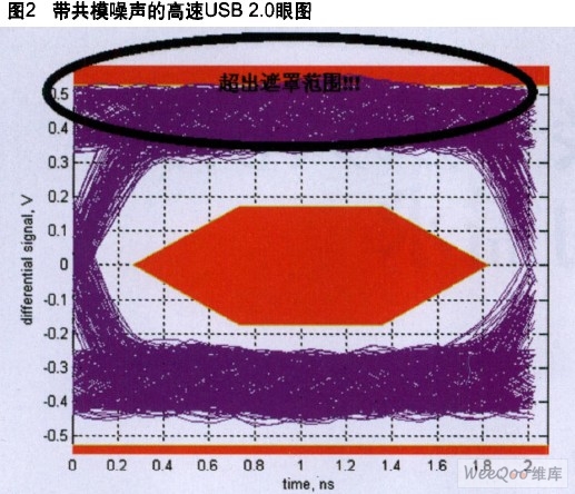
Figure 2 Hi-Speed ​​USB 2.0 Eye Diagram with Common Mode Noise
In Figure 2, the noise exceeds the entire upper limit of the mask, the signal conversion quality drops, and is closer to the excess mask range. In this case, the receiver will not be able to receive the data being transmitted because there is too much noise on the signal, causing the receiver to be unable to effectively distinguish between different states under these conditions. This is still only a small amount of noise, and the amplitude is only 5% of the USB 2.0 signal amplitude.
USB 2.0: Protection Interface
Filtering out EMI/RFI noise is not only important, it is also important to protect sensitive internal circuits from ESD events that can be harmful or even devastating. In these cases, it is necessary to use a common-mode filter with integrated low-capacitance ESD protection, such as ON Semiconductor's NUC2401. This filter provides the necessary bandwidth for high-speed USB 2.0 signals, proper common-mode attenuation, and sensitive internal circuit ESD protection. The integrated ESD protection has a very low capacitance (<1 pF), making the device not appear to the high speed USB signal. Looking at the eye diagram shown in Figure 3, even if a large amount of common mode noise is introduced, it does not exceed the eye mask boundary and maintains signal integrity. This figure shows an eye diagram of the high-speed USB 2.0 signal at the NUC2401 output with a common-mode noise signal frequency of 900 MHz and a peak amplitude of 400 mV.
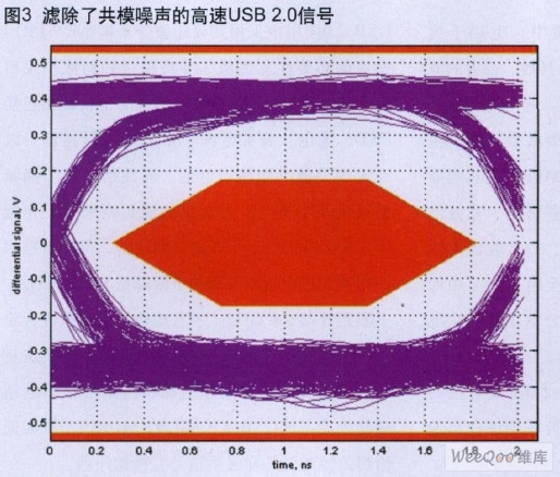
Figure 3 High-speed USB 2.0 signal filtering out common mode noise

The final eye diagram shown in Figure 3 does not extend beyond the upper, lower and intermediate regions of the mask. This is also achieved if the introduced noise amplitude exceeds the noise amplitude in Figure 2 by more than 5 times. Even if the noise reaches such a high level, the receiver can recognize the final eye diagram at the output of the filter and maintain excellent signal integrity.
Filtering is extremely important in many interference environments caused by a large number of sources of interference. The differential interface should help minimize some common mode noise effects, but there are still signal integrity issues as shown in this article. In addition, at a device entry point such as a USB port, noise can disturb other internal circuits if not properly filtered. The best solution to eliminate these noises at the entry point and to cope with any ESD event is to use a common mode filter with integrated ESD protection. Using a common-mode filter like the NUC2401 allows the USB 2.0 interface to be enhanced in terms of EMI/RFI noise cancellation while providing ESD protection. It is important to know that high-speed USB 2.0 signals can affect the signal even if a small amount of EMI/RFI noise is introduced, causing the USB receiver to be unrecognizable.
About baby bib:
The mothers have common perplex that they worry the baby get dirt on clothes when they have meal.What can we do to avoid that? Many mothers will buy baby bib! However, the baby bib which is made of cloth is easy to get dirty and difficult to clean! Can we solve this problem ? Absolutely yes! Silicone Baby Bibs are not only can help you avoid dirty problems when they have meal, but also easy to clean! Why? Because the silicone material is smooth and waterproof, more important , it can dry quickly which save you a lot of time. So, when mothers choose to buy a baby bib, most of them choose the silicone one!
Product discription:
1.Product name: Baby Bibs Silicone , Silicone Bibs For Children ,Waterproof Silicone Baby Bibs,Food Grade Silicone Baby Bibs,Silicone Baby Feeding Bibs,Silicone Baby Bibs With Pocket
2.Place of origin:Guangdong China
3.Color:any pantone color
4.Logo:Printing,debossed,embossed
5.MOQ:500pcs.
6.Package:1 pcs/opp,customized design is available.
7.Design:Customized/stock
8.Certification:FDA,LFGB,SGS,ROHS,etc.
9.Usage:Use in baby meal
10.Silicone baby bibs photos for reference.

Silicone Bibs
Baby Bibs Silicone,Silicone Bibs For Children,Waterproof Silicone Baby Bibs,Food Grade Silicone Baby Bibs,Silicone Baby Feeding Bibs,Silicone Baby Bibs With Pocket
OK Silicone Gift Co., Ltd. , http://www.oemsiliconegift.com