1 Introduction
LED has the advantages of high light quality, low power consumption, long life, environmental protection, etc. It has been widely used in large-screen color display, LCD backlight, landscape lighting, interior decoration, etc., and in automotive lighting, tunnel lighting, general lighting. Applications in other fields have been gradually promoted. The volt-ampere characteristics of the LED are non-linear. The very small fluctuation of the driving voltage can cause a relatively large change in the driving current. The LED has a negative temperature characteristic of the PN junction. When the LED temperature rises, the threshold voltage decreases, and the LED current increases. Heating, the temperature continues to rise, the LED is finally damaged; the luminous intensity of the LED is proportional to the average current flowing through it, so the LED is often in the form of constant current driving [1].
At present, the common constant current driving method of LED adopts a method of detecting current by connecting a detecting resistor in series with a high-power LED circuit, or indirectly feeding current through a voltage across the capacitor to realize constant current control of the LED. No matter which constant current driving method requires feedback closed-loop control, the control loop needs to be designed, the circuit is more complicated, and the reliability is also reduced [2][3]. The series resonant converter has a constant current characteristic and can be used to realize open-loop constant current driving of the LED. At present, the resonant circuit is not widely used in the LED driving power supply. Reference [4] is a voltage source that uses a resonant circuit to provide a high-frequency sine wave voltage; the literature [5] [6] achieves an open-loop constant current through a series resonant circuit. The difference is that the literature [5] makes the series resonant circuit work in the current interrupted state, does not need current sampling, realizes the output current constant current, but the circuit works in the intermittent state, the switching frequency is smaller than the resonant frequency, the current peak is relatively large, and the efficiency is not high. . In [6], the series resonant circuit is operated in a continuous state to realize open-loop constant current. However, the analytical design in the literature ignores the phase difference between the load voltage and the input voltage. Only some of the parameters are designed in this paper.
The two-stage LED driver circuit with power factor correction (PFC) function mainly implements the PFC function from the front stage BOOST structure and provides a stable 400V voltage for the latter stage; the latter stage is a constant current driver. If the latter stage can open the loop to achieve constant current, it will reduce the design complexity and improve the system reliability. For this reason, the series resonant circuit is used in the post-stage constant current driver of this structure. The circuit operates in a continuous state of the resonant inductor current, enabling open-loop constant current. In this paper, the circuit is analyzed to determine the conditions of the open-loop constant current, and the resonance parameters, the switching operating frequency, the number of LEDs that the converter can drive, and the determination of the transformer ratio n are provided. This paper designs according to the analysis and carries out simulation and experiment.
2 Analysis of constant current source
2.1 LED equivalent model
LED is a PN junction optoelectronic device whose volt-ampere characteristics have nonlinear and unidirectional conductivity. When the forward voltage is less than a certain value, the current is very small and does not emit light. When the forward voltage exceeds a certain value, the forward current As the forward voltage increases rapidly, the volt-ampere characteristic model of the LED can be expressed by equation (1) [1].
 (1)
(1)
Where Vturn-on is the LED threshold voltage and Rs is the slope of the volt-ampere characteristic curve. Thereby, an equivalent circuit model of the LED as shown in FIG. 1 can be obtained:

Figure 1 LED equivalent circuit model
2.2 equivalent circuit of constant current source circuit
In this paper, the series resonant circuit with half-bridge structure is taken as an example for analysis and design. The schematic diagram of the resonant circuit is shown in Figure 2. In the figure, n is the transformer ratio, m is the number of LEDs, and the transformer only acts to isolate and transfer energy.
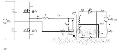
Figure 2 Schematic diagram of the resonant circuit
To simplify the analysis, the secondary side load is converted to the primary side of the transformer according to Figure 2, and a simplified circuit diagram of the resonant circuit is obtained, as shown in Fig. 3.
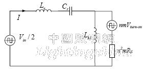
Figure 3 simplified circuit diagram of the resonant circuit
Using fundamental analysis, the fundamental of the input voltage can be obtained:
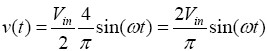 (2)
(2)
The fundamental effective value of the input voltage is:
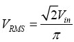 (3)
(3)
The fundamental wave of the resonant current is:
 (4)
(4)
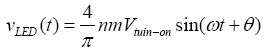
Where θ is the phase difference of the resonant current with respect to the input voltage, and IRMS is the effective value of the resonant current fundamental wave. The fundamental wave of the LED equivalent power supply is:
 (5)
(5)
Since the fundamental wave of the equivalent power supply of the LED is in phase with the fundamental of the resonant current, when calculating the IRMS, the LED can be replaced with the equivalent resistor RLED by the substitution theorem.
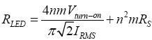 (6)
(6)
And the transformer magnetizing inductance LM is relatively large, and the simplified circuit can be equivalent. The equivalent circuit diagram is shown in Fig. 4.
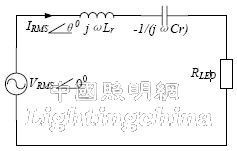
Figure 4 equivalent circuit diagram of resonant circuit
According to Figure 4, the effective value of the resonant current fundamental wave can be obtained:
 (7)
(7)
And the average current flowing through the LED is:
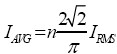 (8)
(8)
So according to the expression (6-8), the average current flowing through the LED can be obtained:
 (9)
(9)
among them: 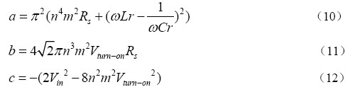
According to the expression (9-11), it can be seen that if the average current flowing through the LED is greater than 0, it needs to be satisfied:
 (13)
(13)
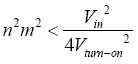
And if the expression (14-15) is satisfied, if the resonant frequency angular frequency ω0, the input voltage Vin, the isolation transformer ratio n, and the resonant inductor Lr are fixed, the average current value flowing through the LED is only the switching angle of the resonant circuit. Frequency related. The specific relationship between the average LED current and the switching frequency can be seen from Figure 5.
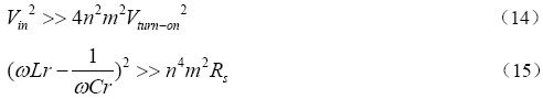
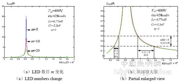
Figure 5 LED average current and switching frequency
As can be seen in Fig. 5(a), in the vicinity of the resonant angular frequency, the average current value of the LED changes significantly as the number of LEDs changes. Fig. 5(b) is a partial enlarged view of Fig. 5(a). It can be seen from the figure that the change in the number of LEDs has a very small influence on the average current value of the LED when the switching frequency is greater or lower than the resonance frequency. The selection range of the switching frequency can be determined according to the operating current range of the LED. For this reason, the expression (14)(15) can be regarded as a condition in which the series resonance circuit realizes an open-loop constant current.