This article refers to the address: http://
I. Experimental content Based on the STM32 platform to control the mobile phone module to make calls, cancel calls and send text messages.
Press the WKUP button to make a call, press the Tamper button to cancel the call, and press the SEL button to send a string of English characters to the phone as a text message.
2. Experimental process
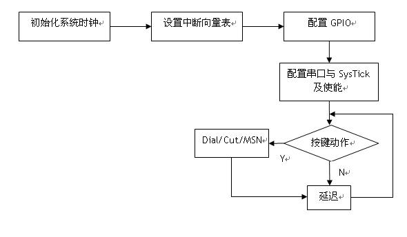
3. Experimental results Press the WKUP button to dial the phone; press the Tamper button to cut off the call; press the SEL button to send a text message to the phone.
Fourth, the realization principle
4.1 The call command is atd+phone number+semicolon+carriage, as long as the serial command is sent to the mobile phone module through the serial port.
Features.
4.2 The cut-off dialing command is ath+carriage, the understanding mode is at+hold (lifting or stopping). Similarly, the corresponding at command dialed is atd.
Solution to at+dial (dial)
4.3 The command to send a text message is a bit more complicated than making a call and closing a call. It is divided into three steps. The first step is to set the format of the SMS message, the second step
Set the mobile phone number to receive SMS, the third step is to write the content of the SMS message. "AT+CMGF=1rn", the role is to set the SMS message to English
Format, the mobile phone module will return "OK rn" after receiving this command, then STM32 will continuously detect the information returned by the serial port until it appears.
The carriage return will proceed to the next step. Then send "AT+CMGS="13800138000"rn" to the mobile phone module, the role is to set the SMS receiving hand.
The machine number, then the mobile phone module will return the ''>'' symbol. Similarly, the STM32 will continuously detect the information received by the serial port until the ''>'' appears.
action. The next step is to send "We are the best team!x1a" to the mobile phone module, "We are the best team!"
The character "x1a" is the ASCII code value of the keyboard "CTRL+Z". This is divided into three steps, each step must be completed before proceeding to the next
Step, if you do not loop to detect the information returned by the serial port, a series of commands sent to the mobile phone module, the mobile phone module will not come, resulting in the loss of the department
The consequences of sub-command.
Main loop:
While(1)
{ //If you press the WKUP button, dial the phone number "13800138000" if(!GPIO_Keypress(GPIO_WKUP, BUT_WKUP))
Serial_PutString("atd13800138000;rn");
While(!GPIO_Keypress(GPIO_WKUP, BUT_WKUP));
/ / If you press the Tamper button, the call is closed if (GPIO_Keypress (GPIO_KEY, BUT_Tamper))
Serial_PutString("ATHrn");
While(GPIO_Keypress(GPIO_KEY, BUT_Tamper));
/ / If you press the SEL button, the MSN () function is called to achieve the purpose of sending SMS if (GPIO_Keypress (GPIO_KEY, BUT_SEL))
MSN();
While(GPIO_Keypress(GPIO_KEY, BUT_SEL));
//The effect of delay is a simple anti-key jitter function Delay(100);
}
Send SMS command:
Void MSN(void)
{u8 word;
Serial_PutString("AT+CMGF=1rn"); //Set the SMS message to English format while(1)
{word=USART_ReceiveData(USART3);
If(word==''n'')
Break;
}
Serial_PutString("AT+CMGS="13800138000"rn"); //Set the number received by the SMS while(1)
{word=USART_ReceiveData(USART3);
If(word==''>'')
Break;
}
Serial_PutString("We are the best team!x1a"); //Write SMS content while(1)
{word=USART_ReceiveData(USART3);
If(word==''n'')
Break;
}
}
V. In-depth analysis of the program
5.1
Each pin that STM32 needs to use needs to enable the pin clock. This program requires three buttons and one serial port (USTAR3), two of which
One button is on the PC port and one button is on the PA port. The program is implemented in the RCC_Configuration() function:
/*Enable GPIOx clock*/
RCC_APB2PeriphClockCmd(RCC_APB2Periph_GPIOx, ENABLE);
/* Enable USARTx clock*/
RCC_APB1PeriphClockCmd(RCC_APB_Periph_USARTx, ENABLE);
/* Enable button pin clock*/
RCC_APB2PeriphClockCmd(RCC_APB2Periph_AFIO| RCC_APB2Periph_GPIO_BUTTON |
RCC_APB2Periph_GPIO_WKUP , ENABLE);
5.2
Each pin of STM32 has a multiplexing function, so each pin used needs to configure the function of the pin.
The GPIO_Configuration() function is implemented inside:
GPIO_InitTypeDef GPIO_InitStructure;
GPIO_PinRemapConfig(GPIO_PartialRemap_USART3, ENABLE);
/* Set USARTx_Tx to multiplex push-pull output at 50MHz */
GPIO_InitStructure.GPIO_Pin = GPIO_TxPin;
GPIO_InitStructure.GPIO_Speed ​​= GPIO_Speed_50MHz;
GPIO_InitStructure.GPIO_Mode = GPIO_Mode_AF_PP;
GPIO_Init(GPIOx, &GPIO_InitStructure);
/* Set USARTx_Rx to a floating input with a frequency of 50MHz */
GPIO_InitStructure.GPIO_Pin = GPIO_RxPin;
GPIO_InitStructure.GPIO_Mode = GPIO_Mode_IN_FLOATING;
GPIO_Init(GPIOx, &GPIO_InitStructure);
/* Set the button pin to a floating input with a frequency of 2MHz */
GPIO_InitStructure.GPIO_Pin = BUT_LEFT | BUT_RIGHT | BUT_UP | BUT_DOWN | BUT_Tamper |
BUT_SEL;
GPIO_InitStructure.GPIO_Mode = GPIO_Mode_IN_FLOATING;
GPIO_InitStructure.GPIO_Speed ​​= GPIO_Speed_2MHz;
GPIO_Init(GPIO_KEY, &GPIO_InitStructure);
GPIO_InitStructure.GPIO_Pin = BUT_WKUP;
GPIO_InitStructure.GPIO_Mode = GPIO_Mode_IN_FLOATING;
GPIO_Init(GPIO_WKUP, &GPIO_InitStructure);
There are three configuration of the pin, Pin, Speed ​​and Mode. When setting USARTx_Tx, all three items are set, but when setting USART_Rx, only setting is made.
Two items, where Speed ​​is not set, keep the last set state, which is 50MHz when USART_Tx is set. The same is in the settings
Three items are set when the bottom and left and the corresponding pins of the Tamper and SEL keys are set, and only two of the corresponding pins are set when the WKUP key is set.
5.3 The last step in the infinite loop of the main function is to call the delay() function to delay 100ms, which is to prevent the jitter of the button. And delay
The implementation of the function is implemented by calling the SysTick clock source overflow interrupt. The SysTick clock source is set to 1ms interrupt at the beginning of the main function.
once.
5.4 The main program communicates with the mobile phone module through serial port 3, and the baud rate is set to 115200. The program is as follows:
USART_InitStructure.USART_BaudRate = 115200;
USART_InitStructure.USART_WordLength = USART_WordLength_8b;
USART_InitStructure.USART_StopBits = USART_StopBits_1;
USART_InitStructure.USART_Parity = USART_Parity_No ;
USART_InitStructure.USART_HardwareFlowControl = USART_HardwareFlowControl_None;
USART_InitStructure.USART_Mode = USART_Mode_Rx | USART_Mode_Tx;
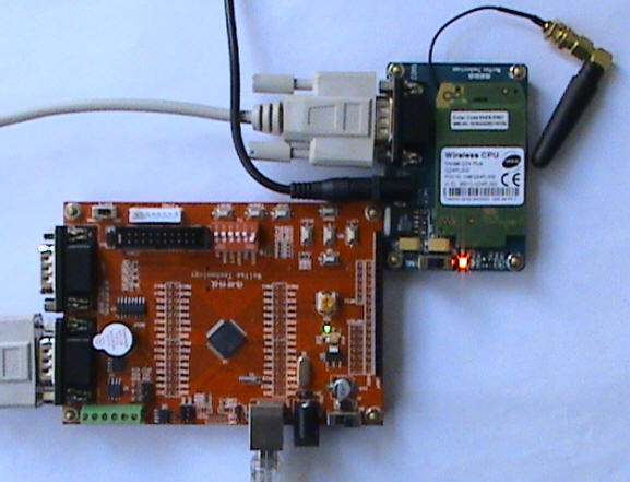
In fact, the mobile phone module also has its communication frequency. If the frequency of the two is different, then the purpose of communication cannot be achieved. Let us now look at how to view and modify the communication frequency of the mobile phone module. The connection of the hardware is very simple. Just connect the power of the mobile phone module, plug in the mobile phone module and the mobile phone card, connect the computer and the mobile phone module with the USB to serial cable, open the SecureCRT software, and set the communication frequency. If the communication frequency set by the software is different from the actual frequency of the mobile phone module, garbled characters will appear in the software window. Now there is a question. If the mobile phone module has just been bought back, I don't know what to do with the communication frequency. Don't worry, if the mobile phone module is not set, its communication frequency is the default data frequency of the first received data. The following example will change the communication frequency of the mobile phone module from 115200 to 57600.
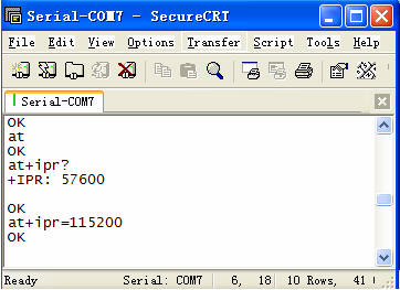
The specific command at+ipr? is to view the communication frequency of the current mobile phone module, and at+ipr=115200 is to set the current communication frequency of the mobile phone module. After the carriage return, the data will be garbled again after entering the data again. Because the communication frequency of the mobile phone module has been modified, it is only necessary to stop the serial port software communication, and then change the communication frequency of the software to 115200.
- STM32 microcontroller Chinese official website
- STM32 microcontroller official development tools
- STM32 microcontroller reference design
Arc Ferrite,High Power Arc Ferrite,Customerized Arc Ferrite
Ningbo Wewinmagnet Co.,Ltd , http://www.wewinmagnet.com