FM radios have been used in high-definition music and voice broadcasts for many years, providing excellent sound quality, signal stability and noise immunity. Recently, FM radio has begun to appear in more market applications such as mobile and personal media players. However, conventional FM design methods must use very long antennas, such as wired headsets, and thus limit the number of users who do not have wired headsets. In addition, with the increasing popularity of wireless usage modes in portable devices, more and more users are hoping to use wireless FM radios with other FM antennas while listening to sound using wireless headphones or speakers.
This article describes an FM radio receiver solution that integrates or embeds an antenna inside a portable device, making the headphone cord an optional accessory. We begin by maximizing receiver sensitivity and then introducing ways to maximize sensitivity, including maximizing the efficiency of the resonant frequency, maximizing antenna size, and maximizing the overall FM bandwidth efficiency with a tunable matching network. Finally, this paper will also propose a tunable matching network implementation plan.
This article refers to the address: http://
Maximizing Sensitivity Sensitivity can be defined as the minimum signal that the FM receiver system can receive and achieve a specific signal-to-noise ratio (SNR). This is an important parameter in the performance of the FM receiving system, which is related to both signal and noise. The Received Signal Strength Indicator (RSSI) can only indicate radio frequency (RF) signal strength at a particular tuning frequency and does not provide any information about noise or signal quality. The audio signal-to-noise ratio (SNR) may be a better parameter when comparing receiver performance using different antennas. Therefore, it is important to maximize the SNR by giving listeners a higher quality audio experience.
The antenna is a bridge connecting the RF circuit and the electromagnetic wave. In the case of FM reception, an antenna is a transducer that converts energy from electromagnetic waves into a voltage that can be used by electronic circuits such as low noise amplifiers (LNAs). The sensitivity of the FM receiving system is directly related to the voltage received by the internal LNA. In order to maximize sensitivity, this voltage must be maximized.
There are a variety of antennas on the market, including headsets, metal stubs, loops and chip antennas, but all antennas can be analyzed with equivalent circuits. Figure 1 shows a generic equivalent antenna circuit model:
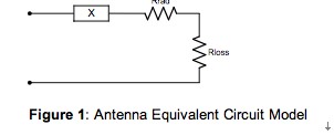
Figure 1: Generic antenna equivalent circuit model.
In Figure 1, X can be a capacitor or an inductor. The choice of X depends on the antenna topology, and its reactance value (inductance or capacitance) is related to the geometry of the antenna. The loss resistance (Rloss) is related to the power dissipated in the form of heat in the antenna. The radiation impedance (Rrad) is related to the voltage generated by the electromagnetic wave. For ease of explanation, this article will analyze the loop antenna model, the same calculations can be applied to other types of antennas, such as short monopole antennas and earphone antennas.
Maximizing Resonant Frequency Efficiency To maximize the antenna's switching energy, we used a resonant network to counteract the antenna's reactive impedance, which may cause the antenna to switch to the internal LNA's voltage value. For inductive loop antennas, the capacitor (Cres) can be used to cause the antenna to resonate at the desired frequency: 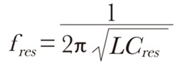
The resonant frequency (Æ’res) is the frequency at which the antenna can convert electromagnetic waves into the highest efficiency of voltage. Antenna efficiency is the ratio of the power of Rrad to the total power of the antenna, expressed as Rrad/Zant, where Zant is the antenna impedance with an antenna resonant network. Zant can be expressed as: 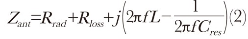
When the antenna is in resonance, the efficiency η can be expressed as:
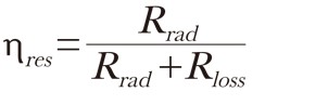
The efficiency at other frequencies is: 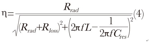
The antenna efficiency η other than the resonant frequency is lower than the maximum efficiency ηres because the antenna input impedance Zant at this time is inductive if it is not capacitive.
Maximizing Antenna Size In order to recover the transmitted RF signal, the antenna must collect as much energy as possible from the electromagnetic waves and efficiently convert the electromagnetic wave energy into a voltage. The energy collected is subject to the available space and size of the antenna in the portable device. For a conventional headphone antenna, which can reach a quarter of the wavelength of the FM signal, it can collect enough energy and convert it into the available voltage of the internal LNA. In this case, maximizing the efficiency of the antenna is less important.
However, as portable devices are becoming smaller and thinner, the space available for embedded FM antennas has become very limited. Although the antenna size has been maximized, the energy collected by the embedded antenna is still very small. Therefore, in the case of using a smaller antenna, it is also necessary to balance the performance without sacrificing performance, and it is more important to improve the antenna efficiency η.
Maximizing FM Band Efficiency with Tunable Matching Networks The FM radio band in most countries has a frequency range of 87.5MHz to 108.0MHz. The FM broadcast band in Japan is 76MHz to 90MHz. In some Eastern European countries, the FM broadcast band is 65.8MHz to 74MHz. In order to adapt to all FM bands in the world, the FM receiving system must have a bandwidth of 40MHz. The traditional solution is usually to tune the antenna to the center frequency of the FM band. However, as shown by the above formula, the efficiency of the antenna system is a function of frequency. This efficiency can reach a maximum at the resonant frequency, but as the frequency deviates from the resonant frequency, its efficiency also decreases. Therefore, since the global FM band has a bandwidth of 40 MHz, the antenna efficiency will be significantly reduced when the frequency is far from the resonant frequency.
For example, if a fixed resonant frequency of 98 MHz is set, then high efficiency can be achieved at this frequency point, but the efficiency of other frequency points will be significantly reduced, thereby reducing the FM performance away from the resonant frequency.
Figure 2 shows the efficiency curves of two antennas (earphone antenna and short antenna) with a fixed resonant frequency in the center band (98 MHz). 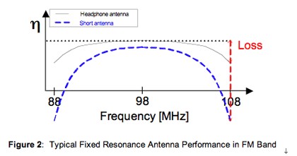
Figure 2: Typical fixed resonant antenna performance in the FM band.
As can be seen from the above figure, the best efficiency can be achieved at 98MHz, but the closer the frequency is to the band edge, the efficiency decreases. This is not a big problem for earphone antennas because the antenna size is large enough to collect enough electromagnetic energy throughout the frequency band and convert it to a higher voltage into the RF receiver. However, compared to longer earphone antennas, the short antenna size is small and the collected energy is small, so the efficiency is also rapidly reduced when the frequency is far from the resonance point. This may cause reception problems when using a fixed resonance scheme at the edge of the band, mainly because the short antenna has a higher 'Q' value than the earphone, making its efficiency extremely low at the edge of the band.
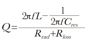
The Q value represents the quality factor, which is proportional to the energy stored in the antenna network per unit time and the loss or radiant energy. For an antenna equivalent circuit with an antenna resonant network, the Q value satisfies:
Compared with the short antenna, the earphone antenna has a high radiation resistance Rrad due to its large size, and therefore also has a lower Q value. Since embedded applications must use short antennas with higher Q values, the problem of drastic efficiency is particularly conspicuous.
The Q value of the antenna is also related to the antenna bandwidth, and the relationship between them can be expressed as:
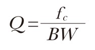
Where fc is the resonant frequency and BW is the 3dB bandwidth of the antenna. Compared to longer earphone antennas, short antennas with high Q values ​​have smaller bandwidths and therefore have higher losses at the edge of the band.
In order to overcome the bandwidth limitation problem of a high-Q fixed resonant antenna, a self-regulating resonant circuit can be used to change the 'fixed resonance to a tunable resonance, so that the circuit is often at a resonant frequency that maximizes the receiving sensitivity. A high signal-to-noise ratio can also be achieved with a self-tuning resonant antenna because the gain from the resonant antenna reduces the system noise figure of the receiver, while the inherently high Q value of the embedded antenna helps to filter out possible local oscillators. Interference with harmonics mixed together.
Construction of a Tunable Matching Network Figure 3 shows a conceptual block diagram of an enhanced FM receiver architecture. The FM receiver architecture can be used to support embedded short antennas, and its tunable resonance is achieved using on-chip tunable variable capacitance and tuning algorithms. 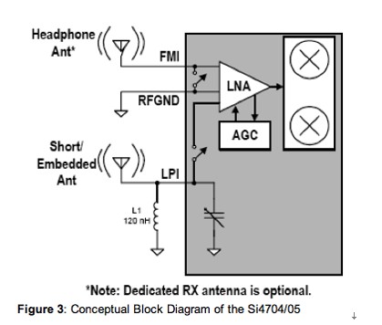
Figure 3: Conceptual architecture diagram of the Si4704/05.
The above design uses a mixed-signal digital low-IF architecture with a digital signal processor (DSP) to create an advanced signal processing algorithm that includes a self-tuning embedded short antenna. The antenna algorithm automatically adjusts the capacitance of the variable capacitor based on each frequency tuning point of the device for optimal performance.
For example, if the user tunes to 101.1 MHz (station 1 in Figure 4), the antenna algorithm will tune the antenna circuit resonance point to 101.1 MHz, thereby optimizing the antenna efficiency and reception performance of 101.1 MHz. When the user tunes to 84.1 MHz (station 2 in Figure 4), the antenna algorithm re-tunes the antenna circuit resonance point to optimize the 84.1 MHz reception performance. 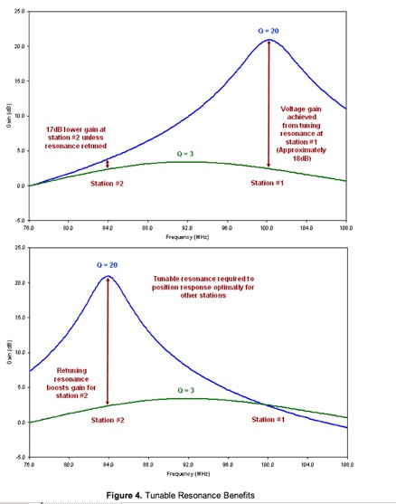
Figure 4: Benefits of tunable resonance.
The tuned frequency is used to adjust the antenna resonance to provide maximum efficiency for each fixed frequency, thereby maximizing the received signal strength over the entire FM band. After using a tunable resonant circuit, the systemicity of using embedded antennas over the entire frequency band has improved. Resonating the antenna at a specified frequency also attenuates interference at other frequencies, significantly increasing the selectivity of the receiver. Therefore, receiver users with embedded antennas are also immune to interference from other unintended sources, which is especially important in urban areas where FM bands are crowded.
Summary As wireless usage patterns become more prevalent in portable devices, more users want to use wireless FM radios with embedded antennas while also listening to programs with wireless headphones or speakers. In order to achieve the goal of maximizing sensitivity, this paper discusses how to improve the FM reception effect using embedded antennas, and further explores its construction method. Since the available space for portable devices with embedded antennas is very limited, a self-tuning resonant network can be considered to maximize the sensitivity of the receiver over the entire FM band, allowing the short antenna to achieve maximum efficiency at each frequency.
Battery Charger,KCA Fast Charger,Intelligent Charger
Jingkesai Electric Co., Ltd. , http://www.hobaoelec.com