Regional grid voltage reactive power optimization control based on multi-region graph control strategy
Aiming at the current situation of voltage and reactive power control in regional power grids, a voltage grid reactive power optimization control scheme based on multi-zone map control strategy is proposed. The scheme uses grid data and remote control remotely collected by regional power grid dispatching automation system or centralized station automation system. The method of adjusting, the on-load voltage regulating tap, reactive power compensation equipment and the excitation current of the local small power plant in each substation are used as control objects, and the multi-zone map control strategy is adopted to realize the automatic control of the voltage and reactive power optimization of the whole network. It can effectively improve the voltage qualification rate of each node of the whole network and reduce the network loss. This paper also discusses several technical problems in implementation, including control parameter tuning, size of reactive power adjustment, how small power plants participate in regulation, and network loss effects in long-distance transmission lines. The control of multi-zone map control is analyzed with examples. effect.
Key words: reactive power optimization; voltage; EMS
Control over OpTImizaTIon of Voltage and ReacTIve Power in the Regional Power Network Based on the MulTI region Chart Control Strategy
Luo Yi, Tu Guangyu, Jin Yanyun, Ding Li, Wu Jixiang
(Huazhong University of Science and Technology, Wuhan 430074, Hubei Province, China)
ABSTRACT: A control scheme for optimization of voltage and reactive power in the regional power network based on the multiregion chart control strategy is proposed to cope with the status quo of the control over voltage and reactive power in the regional power network. The voltage of the entire network and optimization of reactive poser is realized using the power network data 。 。 。 。 。 。 。 。 。 。 。 。 。 。 。 。 。 。 。 The taps and reactive power compensation installations in all substations and the exciting current of generators in small local power plants as the control objects. The adoption of the multiregion chart control strategy for the automatic control of the optimization of the voltage and reactive power of the entire Power network has made it possible to practical increase the rate of acceptab Le voltage at all the nodes on the entire power network and reduce network loss. Also discussed are some technical problems in implementation, such as the setting of control parameters, the magnitude of the amount of reactive power regulation, the way small local power plants take Part in the regulation, the influence of network loss in long transmission lines. The effect of control with the multiregion chart strategy is discussed with examples.
KEY WORDS: Optimization of Reactive Power; Voltage; EMS
0 Introduction After several years of urban farm network transformation in China, the reliability of power supply has been greatly improved. The reliability of power supply in some places has reached 99.9%, which can basically meet the requirements of power supply reliability of most users. Under this precondition, the current regional grid voltage quality (especially the voltage pass rate) problem is particularly prominent, and is increasingly valued by the power supply departments at all levels. There are two main factors affecting the regional power grid voltage pass rate: on the one hand, the reactive power supply configuration is unreasonable, which can be solved gradually with the appropriate amount of construction funds on the basis of the voltage and power optimization calculation of the regional power grid; There is no voltage and reactive power optimization coordination control that can achieve the whole network. At present, many substations in the regional power grid are equipped with voltage and reactive power integrated automatic control device (VQC), which only collects internal information of the substation. The control target is the substation low voltage bus voltage and the reactive power consumed by the substation, which cannot realize the coordinated control of the whole network. . In some areas, the grid EMS is equipped with voltage and reactive power optimization calculation software. In theory, the calculation results can be used to realize the whole network voltage reactive power optimization control, but the application is limited due to some difficult technical problems. Including convergence problems, when the system data is incomplete or after the occurrence of local bad data, the calculation failure, the asynchronous data of the telecontrol data, etc. directly affect the effect of the control. Therefore, it is urgent to propose new control principles and control methods to solve the problem of voltage and reactive power coordination control in regional power grids and improve the voltage qualification rate of regional power grids.
Many scholars at home and abroad have conducted many studies on this. For example, the literature [1] proposed a centralized network reactive voltage optimization centralized automatic control system, which is not a simple grid power flow calculation, but to establish an optimization and control judgment rules that are as small as possible and voltage qualified in the whole network. These rules improve the control effect. In [2], an automatic voltage control method for 110kV and above power grids is proposed. This method is based on the economic voltage difference to optimize the voltage reactive power flow program, and solves the problem of convergence of voltage reactive power optimization calculation software installed in EMS. Have some help.
In this paper, a control theory and control method for voltage and reactive power optimization control of regional power grid based on multi-region graph control strategy is proposed. Using the grid data collected from the EMS or centralized control station SCADA system and the network topology map of the regional power grid, it is not necessary to carry out the regional grid voltage reactive power optimization calculation, and the corresponding control of each substation is controlled by the constructed grid multi-zone map control rules. It can better solve the problem of voltage and reactive power coordination control in regional power grids.
1 Control principle
1.1 The basic idea of ​​voltage reactive power control In order to understand the control idea of ​​voltage and reactive multi-zone map of regional power grid, some basic concepts are defined as follows:
Terminal subnet: In a regional power grid, a network consisting of a voltage-connected device of a certain voltage level and its assigned device becomes a terminal subnet.
Accompanying the terminal subnet: the network of the terminal subnet plus the transformer that supplies power to the terminal subnet.
Terminal Subnet Voltage: The voltage at the highest voltage level in the terminal subnet.
The terminal subnet is reactive: the reactive power circulating on the transformer that supplies power to the terminal subnet.
Terminal subnet reactive power adjustment constraint: When adjusting the reactive power compensation device in the terminal subnet, it should ensure that the terminal subnet reactive power changes within a given range. This restriction condition is called terminal subnet reactive power adjustment constraint.
The general principle of regional grid voltage reactive power control is to minimize the grid network loss under the premise of ensuring the voltage is qualified. In order to make the grid network loss  To achieve the minimum, the reactive power transmitted in the grid should be reduced as much as possible, and the grid operating voltage should be appropriately increased. Therefore, if the reactive power inside the terminal subnets at all levels can be balanced as much as possible, the goal of minimum network loss can be achieved. However, it is impossible to balance the reactive power of each terminal subnet, and it is not necessary. Therefore, many reactive compensation devices must be installed, which is economically unreasonable.
In fact, for the urban power grid, the territorial coverage of the terminal subnet is small, and the line loss is generally negligible. The network loss mainly comes from the step-down transformer. As long as the reactive power flowing through the transformer is reduced to the minimum value, the network can be reached. The smallest target. In this way, the reactive power in the same voltage level grid can be balanced, and the reactive power of each substation in the same voltage level grid can be transmitted to each other without causing too much network loss, and the voltage is relatively easy to meet the requirements.
For rural power grids, the geographical coverage of terminal subnets at different levels is quite different, and the choice of transmission line diameters is not the same. In many cases, the influence of transmission line losses must be considered. Therefore, it is necessary to consider not only reducing the reactive power flowing through the transformer to a minimum value, but also when the local reactive load is large, the mutual support of the reactive power of each substation in the same voltage level grid should be implemented according to the principle of minimum electrical distance. That is, under the condition that the power flow allows, the reactive power compensation device with a small electrical distance from the reactive load is preferentially switched or adjusted. This will ensure that the entire network loss is minimal. This principle can of course also be used in urban power grids, but the effect is not obvious unless there are large reactive devices such as current limiting reactors in the system.
By changing the tap of the on-load tap-changer of each substation, the voltage of the sub-subnet of the low-voltage side of the transformer can be changed, thereby changing the reactive power of the grid. Generally, reducing the tap of the on-load tap-changer can increase the voltage of the sub-substation of the low-voltage side of the transformer, so that the reactive load is increased. Increasing the tap of the on-load tap-changer can reduce the voltage of the sub-subnet of the low-voltage side of the transformer. The reactive load is reduced. However, the number of adjustments of the tap of the on-load tap changer transformer should not be too frequent and should be adjusted in a limited manner. When the terminal subnet has insufficient reactive power, the voltage at each point in the terminal subnet is generally low, and it is not allowed to locally raise the voltage by lowering the tap of the on-load tap-changer, which will cause the reactive power shortage of the entire power grid to be larger. It is necessary to compensate for the reactive power first. At this time, it is possible to first put into the capacitor bank of the substation with low operating voltage and reactive power shortage, or to cut off the reactor of the substation with low operating voltage and reactive power shortage, and then increase the power plant. The reactive power. When the terminal subnet has excess reactive power, the voltage at each point in the terminal subnet is generally high, and generally the reactive power should be reduced. At this time, the capacitor bank of the substation with high operating voltage and reactive power remaining may be cut off first, or The reactor of the substation with high operating voltage and reactive power is put into operation, and the reactive power output of the power plant is reduced.
If you want to switch the reactive power compensation device in a certain terminal subnet, you must first check whether the reactive power of the terminal subnet will exceed the limit. The operation can only be performed when the terminal subnet is not reactive and does not exceed the limit.
1.2 Multi-zone map control strategy From the perspective of grid operation, the voltage and reactive power of each node of the grid should be within a certain range, that is, the voltage and reactive power have upper and lower limits. If UH, UL, QH, and QL are voltage upper limit, lower voltage limit, reactive upper limit, and reactive lower limit, the abscissa indicates the reactive power of the terminal subnet, and the ordinate indicates the voltage of the terminal subnet, as shown in Figure 1. Multi-zone map.
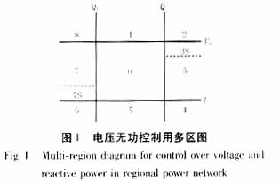
The control strategy for each area is as follows:
Area 1 - The upper limit of the voltage, the reactive power is qualified. The tap is adjusted to step down, but is blocked by the low side voltage limit of the three winding transformer.
Zone 2 - first adjust the tapdown of the tap. If the lower limit is still available, the capacitor is input under the constraint of the reactive power adjustment of the terminal subnet.
Zone 3 - Input the capacitor under the constraints of the terminal subnet reactive power regulation.
Zone 4 - first put the capacitor under the constraints of the terminal subnet reactive power adjustment, if the voltage is still lower limit, adjust the tap boost.
Zone 5 - Adjusts the tap boost, but is blocked by the low side voltage limit of the three winding transformer.
Zone 6 - first adjust the tap boost, if the reactive power is still upper limit, the capacitor is cut off under the terminal subnet reactive power adjustment constraint.
Zone 7 - Cut the capacitor under the constraints of the terminal subnet reactive power regulation.
Area 8 - first remove the capacitor under the constraints of the terminal subnet reactive power adjustment. If the voltage is still upper limit, adjust the tap to step down.
The 3S and 7S zones are anti-vibration zones and are generally uncontrolled. The voltage and reactive power of zone 0 are all qualified.
The meaning of "under the terminal subnet reactive power constraint" in the above strategy is that the adjustment operation is allowed only when the terminal subnet reactive power adjustment constraint is satisfied; otherwise, the adjustment operation is not allowed. The meaning of “locked by the low-voltage side of the three-winding transformer†means that if the operation causes the voltage on the low-voltage side of the three-winding transformer to exceed the limit, the operation is blocked.
1.3 Multi-zone map control process The control process of multi-zone map is shown in Figure 2.
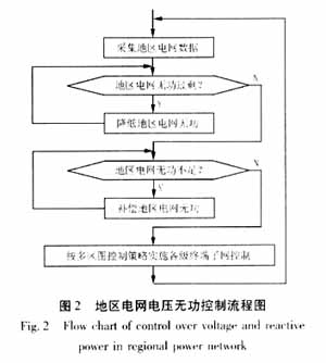
Each adjustment cycle is divided into two phases:
First, judge the overall reactive power level of the regional power grid. If the reactive power is excessive or insufficient, the local power grid is disabled under the constraints of the regional power grid reactive regulation, so that it is in the qualified range or the first phase adjustment is stopped when there is no adjustment means. The first stage adjustment is the basis of the grid voltage reactive power coordination control. If the first stage adjustment is cancelled, the regulation oscillation or the number of adjustments may be excessive due to excessive or insufficient reactive power. In the actual control process, you can consider the first two or three-level terminal subnets as the terminal subnet reactive power balance adjustment, which will produce better results.
Then, according to the multi-region map control strategy, the terminal subnets at all levels are controlled. Generally, the terminal subnet of the upper level should be controlled first, and then the subnet of the next level should be controlled, that is, the voltage level is controlled from high to low. In order to speed up the control process, multiple terminal subnets that operate independently of each other can be simultaneously controlled, and the reactive power adjustment constraints are uniformly determined.
1.4 Control parameter setting control parameters can be adjusted by three methods:
Method 1: Time adjustment method. Firstly, according to the historical load data of the grid operation and the operation requirements of the grid, the voltage and reactive power requirements of the terminal subnets at various stages are calculated, and the multi-zone map of each period is set with this requirement range. The step size of the general time period is in minutes, and the interval can be artificially set. This method is equivalent to giving a statistical voltage curve and a reactive power curve over a period of time, which has the advantages of simple use and easy setting; the disadvantage is that it is difficult to achieve reactive power optimization when the load changes.
Method 2: Load setting method. The load setting method is a method for setting the voltage and reactive power requirements of terminal subnets at different levels under different loads. The setting data is generally given by a multi-dimensional linked list, and load matching is performed online. This method requires reactive power optimization calculations in advance, and it takes a long calculation time to obtain a multi-dimensional linked list. When the system's operating mode changes, it will bring certain errors.
Method 3: Online tuning method. The online tuning method is a quasi-real-time tuning method. When the system operation mode, system load changes, or after each set time (usually minute), the reactive power optimization calculation is automatically performed, and the multi-zone is adjusted by the calculation result. The parameters of the graph, especially the upper and lower limits of reactive power, at this time, the upper and lower limits of the reactive power can be set to an adjustment deviation amount near the optimal reactive power value. which is: 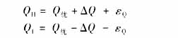
Where: Q is the optimal reactive power value calculated by reactive power optimization; △Q is the maximum adjustment error when reactive power compensation; εQ is the adjustment margin, εQ >0, the smaller the εQ setting is, the more frequently the adjustment is. The more the adjustment, the better the tracking of the optimal reactive value. It can be seen that the adjustment performance of the online tuning method is the best. However, it is necessary to choose a reactive power optimization algorithm with good convergence and calculation speed, such as the economic pressure difference method. Q-optimal calculation may also fail due to incomplete system data or local bad data. It may also cause large errors due to the asynchronous nature of telecontrol data during the change of system operation mode. In actual use, Q-optimal should be judged. rationality. A feasible method is to combine the method 2 and the method 3. If the Q is in the range of the method 2, the setting value of the method 3 is adopted. Otherwise, the setting value of the method 2 is adopted, which is to control the computer memory at the expense. For the price.
1.5 Several special problems There are some special problems that must be considered in the regional grid voltage reactive multi-zone map optimization control, mainly:
(1) How much reactive power should be adjusted at a time when the voltage is unqualified? One method is the sensitivity analysis method, which first calculates the reactive-voltage sensitivity values ​​under several typical loads in various typical operating modes, and matches the closest operating mode and the closest load to select the ones to be adjusted. Reactive power. Another method is the expert system method with self-learning function, which automatically generates the voltage value affected by the reactive capacity of each unit during each stage load in the control engineering (the initial value can also be sensitivity analysis). The method is obtained) and these values ​​are constantly corrected during the control process.
(2) Make full use of local small power plants to participate in the adjustment. Small hydropower plants exist in many regional power grids, and some of them have reactive power regulation capabilities. Small hydropower units are subject to many restrictions, mainly the limits of the terminal voltage and power limit diagrams, but the small hydropower unit has the ability to smoothly adjust the reactive power, and the operating cost due to the adjustment is much lower than the switching capacitor and reactance. Switch maintenance costs caused by the device. Therefore, in the process of reactive power balance adjustment, the adjustment capacity of local small hydropower plants should be utilized as much as possible.
(3) Effects and corrections of large impedance components and heavy-duty lines. Large impedance components and heavy-duty lines will cause large voltage and power losses, and the amount of reactive power transmitted by them should be limited during regulation. The switching method of the reactive power compensation device can be determined according to the distance of the electrical distance according to the principle described in 1.1.
(4) If a substation has insufficient reactive power or low voltage, but the substation has no adjustment means, then other substations or power plants in the same terminal subnet can be considered to support reactive power; similarly, if a substation has reactive excess or voltage bias High, but when the substation has no adjustment means, it can be considered that other substations or power plants in the same terminal subnet have less reactive power. At this time, priority should be given to ensure that the voltage is acceptable.
2 Control effect analysis Compared with the control method of voltage reactive power integrated automatic control device (VQC) installed in multiple substations, the regional grid voltage reactive power optimization control based on multi-zone map control strategy realizes the voltage of the whole network. The coordinated control of the work enables the reactive power to reach or approach the optimal, reduces the network loss, avoids the possible adjustment oscillation between the substations, and plays an important role in ensuring the voltage pass rate.
Compared with the control scheme based on voltage and reactive power calculation software in EMS, the regional grid voltage reactive power optimization control based on multi-region graph control strategy fundamentally solves the problem that the calculation software does not converge, the grid asynchronous data, the grid data is incomplete or partial. The uncontrollable impact caused by bad data is greatly enhanced. However, whenever the grid operation mode changes and the load changes greatly, the control process is not completed once, but there is a regulation period, and the control process is longer than the control scheme based on the voltage reactive power calculation software in EMS.
Due to the remote control system itself, the data of the regional power grid is asynchronous, and the time difference between the data transmitted to the primary station at the same time of the power grid may reach several seconds, and the advanced computing software may have a large error or even no convergence. However, when multi-zone map control is used, the reactive power of a certain point is detected by the terminal subnet reactive power. The terminal subnet voltage detects the voltage of a certain or a few points. If the asynchronous data deviation is large, It will be confirmed by the delay re-detection that the asynchronous data affects the adjustment error, and the influence of this adjustment error will be significantly weakened due to the dispersion of the capacitor capacity value.
If the grid data is incomplete, the control scheme based on the voltage reactive power calculation software in EMS is often unable to be calculated due to the voltage reactive power calculation software, but the multi-zone map control can still achieve the goal of coordinated control in most areas of the grid. Local areas with incomplete data will improve voltage due to the control of the terminal subnet in which they are located.
If local bad data occurs, the control based on the voltage reactive power calculation software in EMS will be wrong. If the feedback data of the first round control is wrong when using multi-zone map control, the control will be blocked, which is equivalent to the grid from the second round of control. Control of data incomplete.
3 Case Analysis Figure 3 is a partial schematic diagram of a regional power grid. The substations and hydropower plants in the picture have been renumbered.
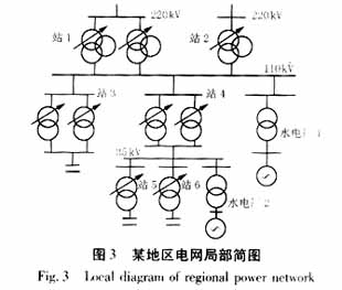
For the terminal subnet where 110kV is located, if the 110kV bus voltage is low or lower, and the reactive power of substation 1 and 2 is close to the upper limit or the upper limit, it can be judged that the terminal subnet of 110kV is insufficiently reactive, and need to be performed. Power compensation. At this time, it is possible to check whether the substation 3, 5, 6 has a substation operating in the 4th zone. If yes, under the premise that the voltage of the low voltage busbar of the corresponding substation is restored from the lower limit and the reactive power of the substation 4 is not reversed, the estimation should be Compensate the reactive capacity and select the capacitor bank input. If the reactive power of the substation 1 and 2 cannot be restored to normal, the excitation current of the hydropower plant 1 is appropriately increased until the reactive power of the substation 1 and 2 returns to normal or the excitation current of the hydropower plant 1 cannot be increased any more. Similarly, if the terminal subnet where 35kV is located is insufficiently reactive, reactive compensation is required, and adjustment compensation can be performed in substation 5, 6 and hydropower plant 2.
After the reactive power balance control of the power grid is completed, the multi-zone map control strategy can be used for control. The order of adjustment is: firstly, the substations 1 and 2 are simultaneously adjusted; secondly, the substations 3 and 4 are simultaneously adjusted; and the substations 5 and 6 are simultaneously adjusted.
If the substation 5 has no adjustment means, the reactive power of the hydropower plant 2 or the substation 6 can be adjusted to achieve reactive mutual support of the same-level power grid, and the voltage is preferentially guaranteed.
4 Conclusion The regional grid voltage reactive power optimization control based on the multi-zone graph control strategy has the following characteristics:
(1) Control the excitation data of the on-load voltage regulation tap, reactive power compensation equipment and local small power plant in each substation by means of the grid data and remote control remote control methods collected by the regional power grid dispatching automation system or the centralized control station automation system. The object adopts the multi-region graph control strategy to realize the coordinated control of voltage and reactive power optimization of the whole network, which can effectively improve the voltage qualification rate of each node of the whole network and reduce the network loss.
(2) Since the voltage and reactive power optimization calculation is not performed, there is no software non-convergence problem, and it can adapt to the asynchronous data of the regional power grid. When the grid data is incomplete or local bad data occurs, the coordinated control of most areas of the power grid can still be realized, and the practicality is greatly enhanced. .
The regional grid voltage reactive power optimization control method based on the multi-zone graph control strategy is suitable for voltage and reactive power control of 110 kV and below.
Coupletetch Co., Ltd. supplies optomechanical product line, including Optical Mount, Crystal Mount, construction components, mechanical devices with electronics. These optomechanical components can be assembled to perform a specific function. Standard components such as posts, rails, translation stages, optic mounts, crystal mounts and BBO Pockels Cell holder are available.
Especially Mirror Mounts, Kinematic Mounts, Fixed optic Mounts, Rotation Mount and Component Mounts are matching our Optical Crystal and EO Q-Switch products.


Crystal Mount,Mirror Framed Mirror,White Round Mirror,Mirror Mount
Coupletech Co., Ltd. , http://www.coupletech.com