1 Introduction
This article refers to the address: http://
The car drum test bench (also known as the chassis dynamometer) is a large indoor car test equipment, which is a bench test system for completing the vehicle test. The traditional drum test bench measurement and control system consists of sensors, multi-channel signal processor, AD/DA converter, industrial control test host and XY curve plotter. The system configuration is more complicated. The program of the measurement and control system is generally composed of VC or other high-level programming languages. Program debugging and parameter modification are cumbersome. The virtual instrument measurement and control system based on Lab Windows/CVI language forms a data acquisition system with sensors, signal conditioning circuits and data acquisition cards. The system calculates the simulated driving resistance, outputs the analog DC voltage signal through the data acquisition card, generates the excitation current through signal processing and circuit conversion, and loads the test vehicle through the synchronous AC motor. The whole measurement and control system has a simple structure, the program design and debugging workload is small, and the test collection and data calculation results are displayed through the industrial computer display. It is an ideal vehicle drum test bench measurement and control platform. In this paper, the measurement and control system of the dynamic test of the drum test bench is taken as the research object, and the application of virtual instrument in the measurement and control system is discussed.
2 Lab Windows/CVI-based car drum test bench measurement and control system
For the test system of vehicle dynamic test, the measurement and control system of the automobile drum test bench can be divided into three modules: 1 data acquisition module, its function is to collect the rotational speed and torque signal of the drum in real time; 2 driving resistance simulation program and transfer Drum test bench function extension program, its function is to process the collected data, calculate the simulated load resistance value and display the output required by the test system; 3 control module, its function is to calculate the simulated resistance value according to the program, through the output signal The processing and circuit conversion generates an excitation current determined by the calibration, and the vehicle is loaded by the AC motor.
The virtual instrument-based drum test bench measurement and control system consists of sensors, data acquisition card, industrial computer and virtual measurement and control software Lab Windows/CVI. The general structure of the system is shown in Figure 1.
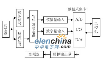
Fig.1 Structure diagram of the measurement and control system of the drum test bench based on virtual instrument
3 Virtual instrument-based data acquisition system hardware
The hardware platform of the virtual instrument consists of a PC computer, a Zhongtai PCI-7333 data acquisition card, and a corresponding sensor.
3.1 Sensor and conditioning circuit
(1) Sensor. The sensor completes the acquisition of the signal, which converts the measured parameter into a corresponding available input signal.
(2) Signal conditioning circuit. In general, sensor signals cannot be directly converted to digital data because the sensor output is a relatively small voltage, current, or resistance change, and therefore must be conditioned before being converted to digital data. Conditioning is to amplify, buffer or calibrate the analog signal to match the range of the data acquisition card. The analog signal is then digitized by the A/D converter of the data acquisition card and sent to a microcontroller or other digital device for data processing of the system.
3.2 Data Acquisition Card and Virtual Instrument Hardware Platform
This experimental system uses Zhongtai PCI-7333 data acquisition card. The PCI-7333 multifunction data acquisition card is suitable for PC series microcomputers that provide PCI bus slots. It has 16 analog input channels, 2 analog output channels and Plug and Play (PnP). It provides the dynamic link library file Usb7K7kC.dll, and the encapsulated functions can be called directly by other applications at runtime.
The analog signal collected by the torque sensor is sent to the analog channel of PCI-7333. The data result after A/D conversion is read out by the USB bus after the first-in first-out memory buffer; the speed signal is sampled and shaped by the speed and then passed through the 16-bit word of the acquisition card. Long count/timer interface output.
4 Drum Test Bench Output Control - Simulating Driving Resistance Principle
Resistance loading is a major component of the drum test bench to simulate road running resistance. The control module of the drum test bench is the simulated resistance value calculated according to the program, and the excitation current is generated by the output signal processing and the circuit conversion, and the vehicle is loaded by the AC motor.
4.1 Mathematical model of vehicle road test driving resistance
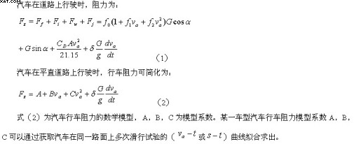
4.2 Mathematical model of vehicle test driving resistance
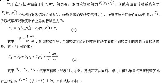
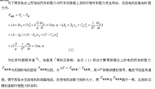
4.3 Drum test bench loading resistance control
5 Software design of measurement and control system for drum test bench based on Lab Windows/CVI
Lab Windows/CVI is a standard C-based visual and interactive virtual software development tool developed by National Instruments of the United States. It has a standard Windows-style interface and can run under a variety of operating systems. It not only has a rich library of functions. It also integrates various professional measurement and control tools and provides superior hardware interface functions. Based on this environment, various resources can be fully utilized to configure the system structure to achieve the optimal system and lowest cost.
In a virtual instrument, using the same hardware system, different software programming can be used to achieve completely different measuring instruments. For the multi-function test requirements of the drum test bench dynamic test, the user can combine one or multi-function universal modules according to the needs of each test function, and call different software modules to complete different test tasks. . Drum test bench measurement and control system Lab Windows / CVI program has three basic tasks: 1 through software programming to design various measurement modules, to complete the programming of various measurement tasks; 2 through the software programming output AC motor required excitation current amplification Signal, control the loading of the AC motor; 3 design the corresponding panel for each test function module, and design the display system according to the test requirements of the drum test bench. Figure 2 is a front panel diagram of the measurement and control software for the car drum test bench.
Figure 2 car drum test bench measurement and control software front panel 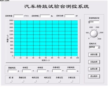
5.1 Signal Acquisition Module
Lab Windows/CVI provides drivers for most data acquisition cards, buses and other related devices. As long as the driver is installed, you can call the relevant functions to complete the initialization and configuration of the device. For the Zhongtai USB7333 data acquisition card, since the instrument driver provided by Lab Windows/CVI cannot be directly driven, the port input function inp ( ), inpw ( ) and port output function outp are provided by the direct operation port address method. ( ), outpw ( ) directly operate on the system board port to achieve the underlying I / O driver 5.2 load resistance calculation module
The input of the load resistance calculation module is the model coefficient, the vehicle speed, the drum radius, the vehicle mass, and the mass conversion factor obtained by the sliding experiment. The function of this module is to discretize the velocity signal by equal distance to generate a series of series, then differentiate each adjacent two points of the generated series, approximate the derivative at the midpoint of the segment, and then output the derivative of each point as the angle. Acceleration series. After obtaining the acceleration value, the simulation load resistance calculation formula can be used to calculate the simulated load resistance as the output of the module. The principle of loading resistance calculation is shown in Figure 3.
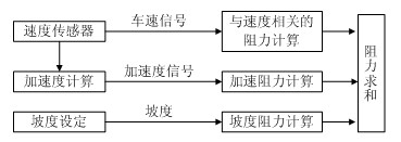
Figure 3 Schematic diagram of loading resistance calculation
5.3 Control Signal Output Module
The mathematical model of the permanent magnet synchronous motor in the two-phase coordinate system shows that the output electromagnetic torque of the AC motor has a linear relationship with the axial component of the stator current when the pole pair and back EMF coefficients are constant. That is, a certain simulated load resistance torque corresponds to a certain magnitude of the simulated excitation current. The simulated load resistance torque calculated by the running resistance calculation module is the output signal of the control quantity, and after the output quantity is calibrated, the corresponding analog excitation current is obtained. The resulting excitation current signal will be output to the signal processing and circuit conversion system through the designated data acquisition card output channel.
6 Conclusion
The drum test bench measurement and control system constructed by virtual instrument technology is mainly composed of data acquisition system and load resistance simulation program based on Lab Windows/CVI. On the hardware platform of the ordinary PC, after the hardware and software of the virtual instrument are configured, the loading resistance of the simulated vehicle can be controlled in real time by the loading device, thereby accurately simulating the driving condition of the vehicle. Compared with the measurement and control system of the traditional drum test bench, the measurement and control system based on virtual instrument technology has a simple structure, and the hardware driver has corresponding supporting software to support it. At the same time, the programming workload based on Lab Windows/CVI is relatively small, which is easy to debug and modify. The drum test bench demonstration system composed of virtual instruments can also be displayed in real time by means of the display of the ordinary PC, and the data storage and printing can also be conveniently completed by the corresponding function modules of Lab Windows/CVI.
Gigabit Ethernet Switch is an L2 function Gigabit Media Converter with the switch function. It is equipped with Gigabit TP ports that accommodate optional 10/100/1000Base-T, and fiber port with a 1000M SFP or a SC 1*9 module. All ports support the functions of full wire-speed non-blocking switch and interface AUTO-MDI/MDIX, also support up to 1k of the MAC address and VLAN. It complies with the standard of IEEE 802.3, IEEE 802.3x, IEEE 802.3u, IEEE 802.3z, IEEE 802.3ab, which greatly increase the flexibility and reduces the cost of network's establishment.
Gigabit Ethernet Switch
Gigabit Ethernet Switch,Ethernet Switch Outdoor,Gigabit Switch,10/100/1000M Network Switch ,Gigabit Ethernet Network Switch
Shenzhen N-net Technology Co.,Ltd , http://www.nnetswitch.com