Introduction Audio signal analyzers use the principle of spectrum analysis to analyze the frequency, spectrum, and waveform of a signal under test. Commonly used spectrum analysis methods are: sweep frequency method, digital filtering method, FFT method. Here, an audio signal analyzer design scheme based on FFT method is proposed. The measured audio signal is converted from time domain signal to frequency domain signal by fast Fourier transform (FFT), and it is decomposed into discrete frequency components. Based on this, various analyses are performed to achieve the same effect as traditional spectrum analyzers. The system design can be applied to audio production, signal analysis and other fields, with certain scientific value and practical value.
This article refers to the address: http://
2 Program argumentation
2.1 Pre-stage signal conditioning scheme Considering to maximize the dynamic range of the signal, and to ensure measurement accuracy and minimize inter-channel interference, the system design uses multiple multi-stage amplifiers to amplify different fixed multiples of the signal to make the signal reach A. The range of /D sampling accuracy is reduced by the corresponding multiple during data processing to obtain the correct amplitude of the signal. The interference between channels in this scheme is small, but the hardware part of small signal amplification is more complicated.
2.2 Frequency component detection scheme The system design uses frequency domain processing. First, the signal A/D is sampled, and then the FFT processing is performed to obtain the signal spectrum, so that the amplitude and power of each frequency component can be conveniently obtained. However, for non-periodic signals, due to signal truncation, spectral leakage and fence effect will be introduced to introduce errors, but the error can be reduced by windowing or increasing the number of FFT operations. The program is based on the fast data processing platform of the single-chip AT89S52 and FPGA. It adopts the frequency domain processing method with high precision and fast speed.
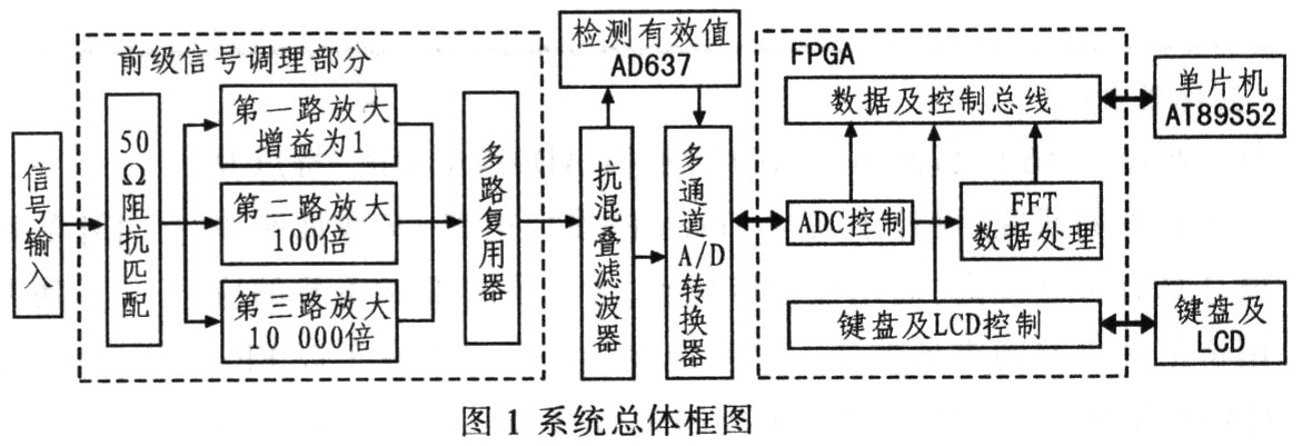
3 system overall design The system uses a combination of single-chip and FPGA as the core of control and data processing. In particular, the system should pay attention to small signal processing, multi-channel grading and amplification, and conditioning to the input range suitable for sampling of the A/D converter. After anti-aliasing filtering, it is sent to the AD637 for RMS detection to calculate the total power, and the other is sent. The A/D converter is sampled. The sampling rate is determined based on the frequency resolution of the root. Based on the fast data processing capability of the FPGA, the power spectrum of the signal is obtained by performing an FFT operation of 4 096 points, and the total power of the signal and the power of the main frequency component are displayed in real time. The system uses the relevant principle to judge the signal periodicity and measure the period, and has the function of power-down storage playback display and signal spectrum display. The overall block diagram of the system is shown in Figure 1.
3.1 Preamplifier circuit Three-way multi-stage amplifier is used. When the actual circuit is debugged, the amplifier circuit of the system can work stably with a gain of 10,000. Because the A/D sampling device used has a very good conversion performance at 100 mV, the minimum signal peak-to-peak value that the system can measure is 100 mV/10 000=10 μV. Finally, the system sets the input signal voltage range from 10μV to 20V, which is the dynamic range of 126 dB.
The gain of the amplifier in the system is large, especially the small signal amplification, so the choice of the op amp is the most critical, otherwise it will affect the overall performance of the system. As shown in Figure 2, the preamplifier uses TI's THS4031 with a noise voltage density of 16 nV/Hz and a bandwidth of 100 MHz. The overall performance is good, suitable for small signal high gain amplification. The rear stage op amp uses the UA741CN, which is a precision low-noise op amp with a bandwidth of 1 MHz and a small bandwidth to further filter out high-frequency components.

3.2 A / D sampling circuit A / D sampling circuit shown in Figure 3, the system uses a 12-bit A / D converter MAX197 to achieve data acquisition. It has 0 to 5 V, 0 to 10 V, -5 to 5 V, -10 to 10 V input ranges, and the sampling rate can reach 100 kS/s. At the same time, there are 8 analog channels, which can be easily selected, and the input range can be selected according to the final amplitude of each channel.
|
5 Conclusion The FFT is used to realize the spectrum analysis of the audio signal. The frequency coverage is 20 Hz to 10 kHz. Using the sampling frequency of 20.48 kHz, the FFT calculates the number of points to 4 096 points, and the frequency resolution is 5 Hz. The audio signal analyzer successfully realizes various design indicators, and also has the functions of power-down storage playback display and spectrum display, which makes the system more intelligent and humanized. The whole system consists of single-chip microcomputer and FPGA and simple hardware circuit. The control is simple, the design cost is low, and it has high scientific value and practical value. |


Energy Saving Bulbs,Energy Saving Lights,4U High Power Lamp,Mini 4U Energy Saving Lamp
Qianghui Lighting Electronic Appliance Co., Ltd. , http://www.ledelamps.com