In the electronic product project, the selection of the single-chip microcomputer can be described as a benevolent person who sees the wise and sees wisdom. The price of Hetai MCU is moderate and the types are quite complete. Here is a comprehensive introduction to the holtek microcontroller.
Holtek microcontroller is designed and developed by Holtek Semiconductor. Holtek is a leading manufacturer of professional microcontroller ICs in China. Its business scope mainly includes the design, development and sales of microcontroller ICs and their peripheral components. Since its establishment in 1998, the company has been committed to the research and development of new products and technological innovation, coupled with the grasp of market trends, can provide the most competitive IC products in the electronics market. The product range includes: general-purpose and dedicated microcontrollers (MCUs), in addition to general application areas, covering various fields such as voice, communication, computer peripherals, home appliances, medical, automotive and security monitoring, and A range of microcontroller peripheral components, such as power management and non-volatile memory, provide customers with a more competitive and complete solution.
Holtek microcontroller - classification(1) HT48 Series I/O Type ( + LCD)
(2) HT49 Series I/O + LCD Type
(3) HT46 Series I/O+AD Type (+ LCD)
(4) HT47 Series I/O+RC-F(AD)+LCD+IR Type
(5) HT48xAx\HT49xAx series Remote (for remote control) type
(6) HT95R2x\HT95R3x Series Phone ( + LCD)
(7) HT45R3x\BS28xx\BS26xx series Touch type
(8) Flash type (HT46Fxx\HT48Fxx\HT66Fxx\HT68Fxx)
(9) TIny Power type (HT56R2x, HT56R6x, HT56R6xx)
(10) Keyboard/Mouse series, USB Audio series,
Voice/Music series, VFD series... .
HOLTEK MCU - System Structure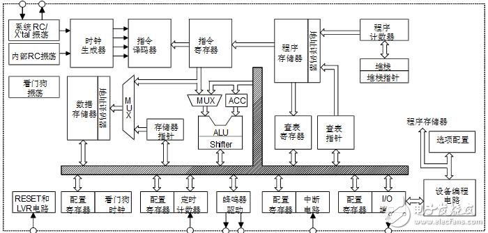
Holtek microcontroller system structure
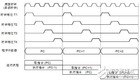
Timing and pipeline structure
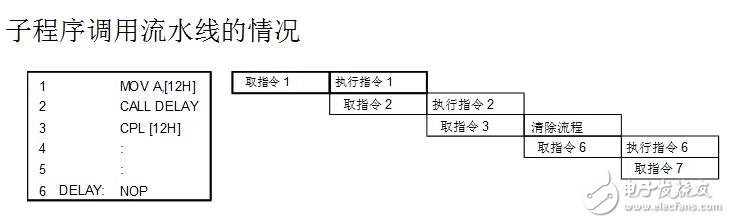
The subroutine calls the pipeline
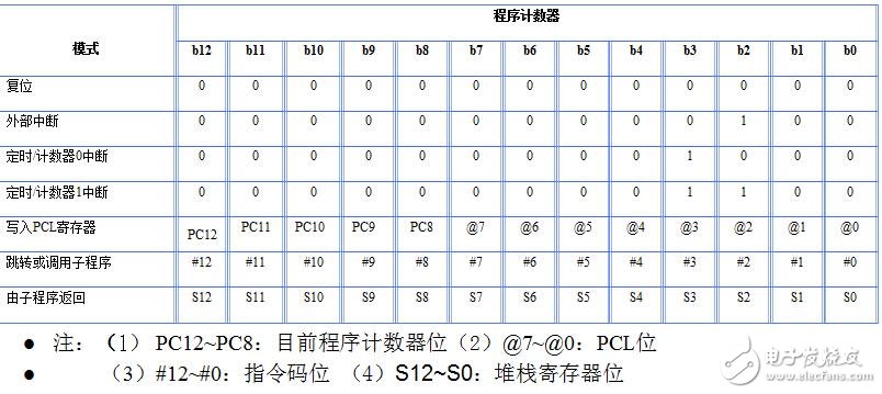
Program counter
The functions provided by the ALU and its associated scripts are as follows:
Arithmetic operations: ADD, ADDM, ADC, ADCM, SUB, SUBM, SBC, SBCM, DAA
Logical operations: AND, OR, XOR, ANDM, ORM, XORM, CPL, CPLA
Shift: RRA, RR, RRCA, RRC, RLA, RL, RLCA, RLC
Increase and decrease: INCA, INC, DECA, DEC
Branch judgment: MP, SZ, SZA, SNZ, SIZ, SDZ, SIZA, SDZA, CALL, RET, RETI
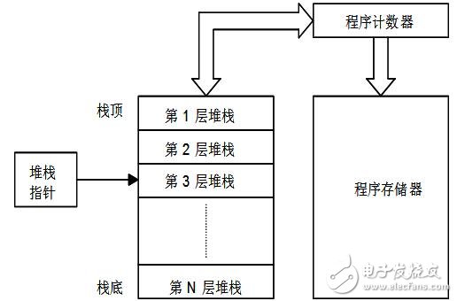
Stack with stack pointer/program counter
HOLTEK MCU - Memory (Program Memory / Data Memory)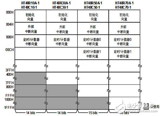
Holtek Semiconductor I/O type MCU program memory structure
The first part is a special function register with a fixed address and is closely related to the correct operation of the microcontroller. Most of the special function registers are directly readable and writable under process control, but some are reserved for future expansion and are not open.
The second part of the general purpose data memory is reserved for the user and can be read and written under process control.
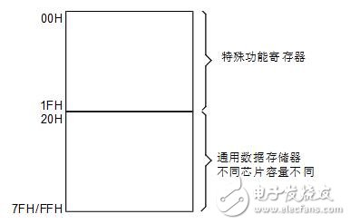
Data memory
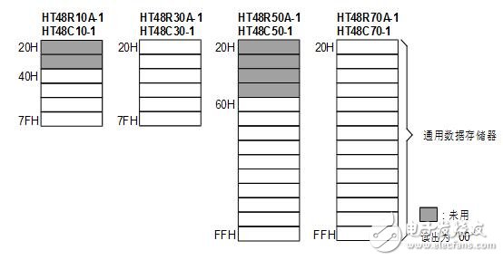
General data memory structure
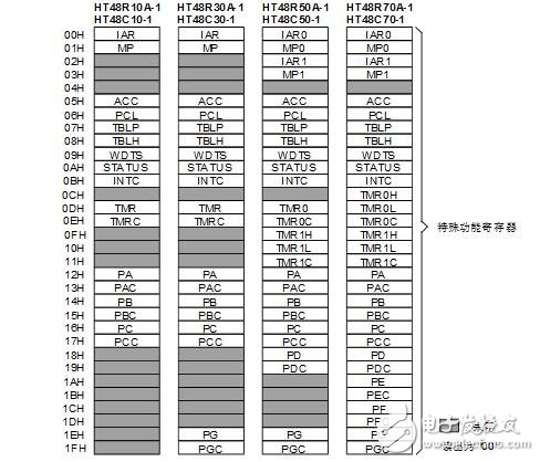
Special register structure
Special function registers:
Indirect Addressing Register – IAR, IAR0, IAR1
Indirect Addressing Pointer – MP, MP0, MP1
Accumulator (data memory address: 05H) – ACC
Program Counter Low Byte Register (Data Memory Address: 06H) – PCL
Table Register (Data Memory Address: 07, 08H) – TBLP, TBLH
Watchdog Timer Register (Data Memory Address: 09H) – WDTS
Status register (data memory address: 0AH) – STATUS
Interrupt Control Register (Data Memory Address: 0BH) – INTC
Timer/Counter Register (Data Memory Address: 0CH~11H)
Input/output port and control register
HOLTEK MCU - Basic I/O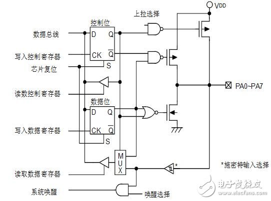
Above: Input/output port hardware diagram
Pull-up resistor (configuration option setting or software setting)
Wakeup function (configuration option setting or software setting)
Input/output port control register
External interrupt input
External Interrupt
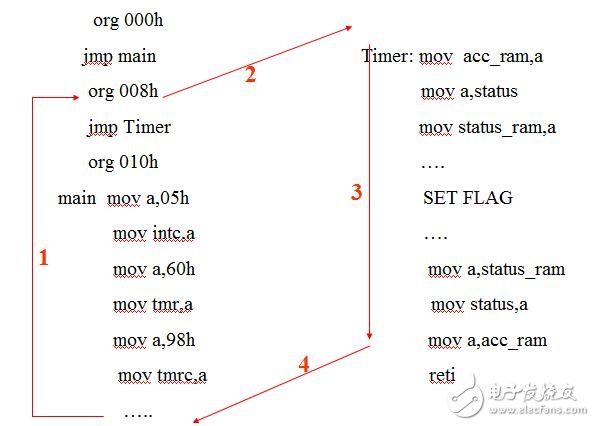
The external interrupt is triggered by a high-to-low transition on the port, after which the corresponding interrupt request flag (EIF; bit 4 of INTC) is set. When the interrupt is enabled, the stack is not full and an external interrupt is generated, a subroutine at address 04H is called. The interrupt request flag, EIF, will be cleared, and the EMI bit will be cleared to mask other interrupts.
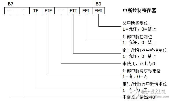
l interrupt control register (a timer / counter)
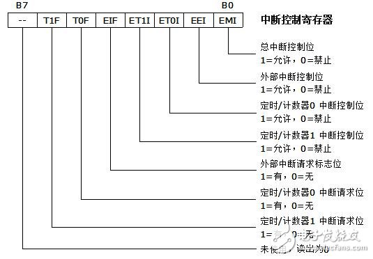
Interrupt control register (two timer counters)
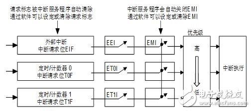
Allowable bits for different interrupts, request flag priority
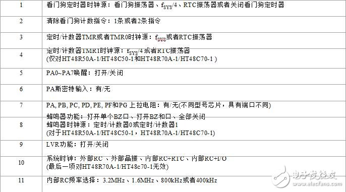
Note: In the figure, the T0F and T1F interrupt request flags and the ET0I and ET1I interrupt enable bits are provided to the HT48R70A-1/HT48C70-1 and HT48R50A-1/HT48C50-1 because they have two timer/counters. The HT48R10A-1/HT48C10-1 and HT48R30A-1/HT48C30-1 have only one timer/counter. The Timer/Event Counter 0 represents the unique Timer/Event Counter TMR and has the Interrupt Request Flag bit, TF, and the Interrupt Enable bit, ETI.
HOLTEK microcontroller - timer / counter interruptWhen the Timer/Event Counter overflows, the Timer/Event Counter Interrupt Request flag will be set and the Timer/Event Counter interrupt will occur. In a microcontroller with only one timer/counter, this bit is the 5th bit of the INTC register, TF. In a microcontroller with two timer/counters, the Timer/Event Counter 0 interrupt request flag is the 5th bit of the INTC, T0F. The Timer/Event Counter 1 interrupt request flag is the 6th bit of the INTC, T1F. When the main interrupt bit is turned on, the stack is not full, and the associated internal interrupt enable bit is turned on, an internal interrupt occurs when the timer/event counter overflows. For a microcontroller with only one timer/counter, the subroutine at address 08H will be called. For a microcontroller with two timers/counters, the Timer/Event Counter 0 interrupt will call the subroutine at address 08H, while the Timer/Event Counter 1 interrupt will call the subroutine at address 0CH. When an internal interrupt occurs, the interrupt request flag, TF, T0F, or T1F, is cleared, and the EMI bit will be cleared to mask other interrupts.
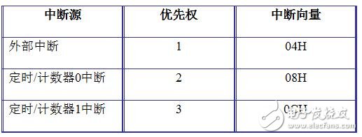
Interrupt priority
Note: This table applies to the HT48R70A-1/HT48C70-1 and HT48R50A-1/HT48C50-1, which have two timer/counters, TMR0 and TMR1. The HT48R10A-1/HT48C10-1 and HT48R30A-1/HT48C30-1 have only one timer/counter, and the timer/counter 0 represents a unique timer/counter, TMR.
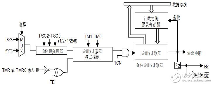
8-bit timer/counter structure
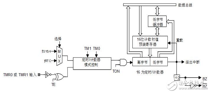
16-bit timer/counter structure
Timer/Counter related registers (continued)
Timer/Counter Control Register – TMRC, TMR0C, TMR1C
Configure the timer/counter input clock source
Timer/Counter Registers – TMR, TMR0, TMR0L/TMR0H, TMR1L/ TMR1H
Timer mode
Event count mode
Programmable Frequency Divider (PFD) and Buzzer Applications
TIMER application example:
TMR is a register that counts up
l When timing or counting, when counting to OFFH, another CLK will be sent, the counter will overflow (the TIMER interrupt will occur when the interrupt is turned on and the stack is not full), the counter reloads the initial value, and starts from this initial value. Recount.
Register TMR or TMR0L/TMR0H write initial value
The control register TMRC sets the operating mode, clock, trigger condition, and switch.
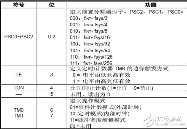
TMRC Control Register
TIMER timing mode
Time calculation in TIMER timing mode
(take the above program as an example)
Condition: OSC : Crystal = 4 MHz
Timer source: system clock
Calculate the time interval T=?
PSC2 PSC1 PSC0 = 000
f INT = fsys/2 = 2MHZ
t = 1/ f INT = 0.5us
T= (256-96)* t=160*0.5us= 80us
TIMER counting mode
a) Set the TMRC to
The TM1 TM0 = 01 timer operates in the timing mode. The counting mode is the same as the timing mode except that the clock source selection of the counter is different.
b) the clock source of the counter is chipped
TMR pin input.
c) TE = 0 rising edge count / 1 falling edge count
TIMER pulse width measurement mode
(a) Set TM1 in TMRC, TM0=11
TE = 0 pulse width falling edge start count / 1 pulse width rising edge starts counting
TO=1 pulse width measurement starts, it will be cleared to 0 after measurement, and this bit must be reset again after measurement
(b) If TO, TE=1, the rising edge of the pulse on the TMR pin starts counting, and the falling edge stops counting. The measurement results are stored in the TMR.
Programming considerations
When the timer/event counter is running in the timer mode, the clock source of the timer is the internal system clock or RTC, which can be synchronized with all operations of the microcontroller. In this mode, when the timer register overflows, the microcontroller will generate an internal interrupt signal to cause the program to enter the corresponding internal interrupt vector. For pulse width measurement mode, the counter's clock source also uses the internal system clock or RTC, but the timer only performs the action when the correct logic condition occurs on the external timer/event input pin. When this external event is not synchronized with the internal timer clock, the microcontroller will only see this external event when the next timer clock arrives, so there may be a small difference in the measured value, which requires the programmer to apply it in the program. Pay attention to it. When the timer is configured for the external event count mode, its clock source is an external event and is not synchronized with the internal system clock or the timer clock.
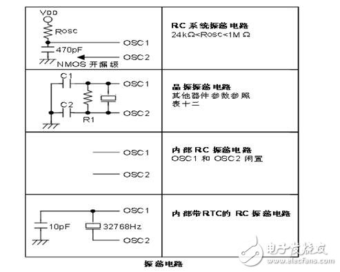
Holtek microcontroller - oscillatorl Three system clocks are available: the watchdog timer also has a variety of clock source options, plus a real-time clock RTC
l Three methods to generate the system clock: use an external crystal / ceramic oscillator, external RC circuit or internal RC clock source
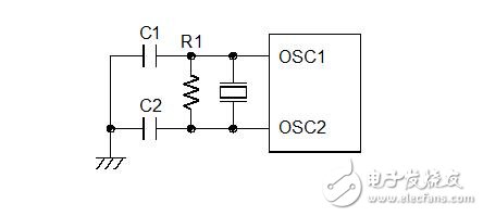
Crystal/ceramic oscillator
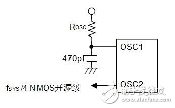
External RC oscillator
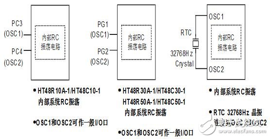
Three kinds of oscillation circuits
RTC oscillator
If RTC is selected as the clock source of the timer/counter, the timer/counter will still work effectively even if the microcontroller is running at HALT. When the timer overflows, a normal internal interrupt signal will be issued. This signal causes the microcontroller to go from the HALT state. It is woken up and continues to work normally until the next "HALT" instruction is executed.
Watchdog timing oscillator
The WDT oscillator is a fully independent RC oscillator that operates freely on the chip. It typically has a cycle time of 65us at 5V and requires no external components. When the microcontroller enters the power-down mode, the system clock will stop, but the WDT oscillator continues to move freely and keeps the watchdog active. To reduce power consumption in some applications, the WDT oscillator can be turned off by a configuration option.
System pause and wake up
The suspend mode is implemented by the "HALT" instruction and results in the following:
System oscillator will be turned off
The data on the RAM chip and registers remains unchanged
If the WDT clock source is from the WDT oscillator, the WDT and WDT prescaler will be cleared and then recounted.
All input/output port status remains the same
The PDF flag is set and the TO flag is cleared.
Holtek microcontroller - watchdog timer and power saving modeThe watchdog timer is used to prevent the microcontroller from crashing or entering an infinite loop. Generally used in harsh environments.
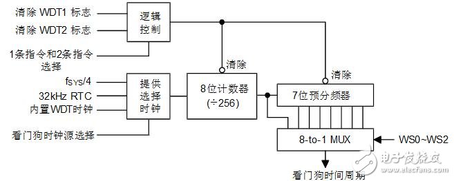
Watchdog timer
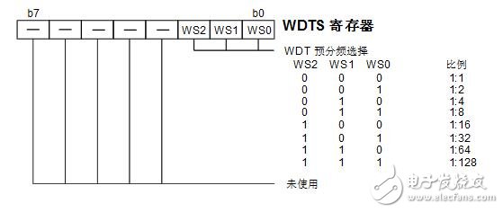
WDT prescaler
Watchdog timer operation:
Take HT48R30A-1 as an example
The WDT clock source can be selected:
a) WDTOSC (12Kz)
b) T1 (system clock/4)
c) RTCOSC (32
Watchdog clearing:
Method 1: CLR WDT
Method 2: CLR WDT1...CLR WDT2
The configuration option selects the clear mode and must be cleared before the WDT counter overflows, otherwise the WDT overflow Reset system will occur.
Configuration options:
Basic circuit reference / technical parameters
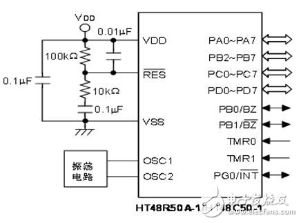
Basic application circuit
HT48 I / O microcontroller technical parameters:
Technical features: high performance RISC architecture, low power fully static CMOS design
Operating voltage: from 4V, from 2.2V to 5.5V, at 8MHz, from 3.3V to 5.5V,
Power loss: 2 mA/1.5 mA (Enhanced I/O) at 5V/4MHz
Standby current is less than 1uA at 3V when the watchdog timer and RTC are not used
Temperature range: operating temperature -40-85 degrees (industrial grade), storage temperature -50-125 degrees
Kernel features:
Program memory
l1K×14 OTP/Mask ROM (HT48R10A-1/HT48C10-1)
l2K×14 OTP/Mask ROM (HT48R30A-1/HT48C30-1)
l4K×15 OTP/Mask ROM (HT48R50A-1/HT48C50-1)
l8K×16 OTP/Mask ROM (HT48R70A-1/HT48C70-1)
Data memory
L64×8 SRAM (HT48R10A-1/HT48C10-1)
L96×8 SRAM (HT48R30A-1/HT48C30-1)
L160×8 SRAM (HT48R50A-1/HT48C50-1)
L224×8 SRAM (HT48R70A-1/HT48C70-1)
Peripheral characteristics:
From 8 to 56 bidirectional input and output ports with pull-up function
PA port has wake-up function
External interrupt input
Event count input
Timer with prescaler and interrupt function
Watchdog Timer (WDT)
Pause and wake-up features save power
PFD/buzzer drive output
Chip built-in crystal and resistor-capacitor oscillation circuit
Low voltage reset
32768Hz real-time clock (RTC) function
Has low voltage reset (LVR) characteristics
With programming circuit interface and program code protection
Mask version of the microcontroller is suitable for mass production
Provide efficient hardware and software support tools
Table reading function
Multi-layer hardware stack
Direct and indirect data addressing modes
Bit manipulation instruction
63 powerful instructions
Most instruction execution time requires only one instruction cycle
Pin assignment:
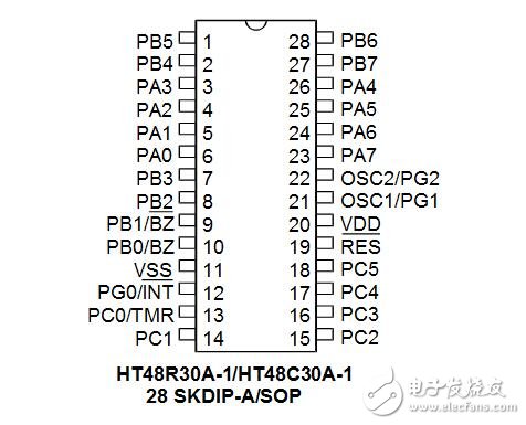
HT48R30A-1/HT48C30A-1 pin assignment
KNB6-63 Miniature Circuit Breaker
KNB6-63 Mini Circuit breakers, also named as the air switch which have a short for arc extinguishing device. It is a switch role, and also is a automatic protection of low-voltage electrical distribution. Its role is equivalent to the combination of switch. Fuse. Thermal Relay and other electrical components. It mainly used for short circuit and overload protection. Generally, According to the poles, mini Circuit breaker can be divided into 1P , 1P+N , 2P, 3P and 4P.
KNB6-63 Miniature Circuit Breaker,Electronics Miniature Circuits Breaker,Automatic Miniature Circuit Breaker,Mini Circuit Breaker
Wenzhou Korlen Electric Appliances Co., Ltd. , https://www.korlen-electric.com