Abstract: This paper introduces the mathematical model of car rollover, analyzes the key factors causing the car rollover, and uses the ADXL203 to design the circuit for measuring the roll angle and data processing through the microcontroller. A portable car rollover warning system based on dual-axis accelerometer is designed to realize the function of dynamically reminding the driver of the current car running state. The test results show that the system has high running speed, accurate measurement, real-time monitoring of vehicle running attitude measurement, and realization of rollover warning function. The circuit has the advantages of simple structure, high precision, small volume, and the like, and can be widely applied to various motor vehicle operating state monitoring fields.
This article refers to the address: http://
introduction
With the increase of car ownership and the increasing speed of cars, the driving safety of automobiles has attracted more and more attention. At present, the vehicle attitude monitoring system based on various sensors and information processing systems is gradually applied to various types of vehicles. It is an important development direction of smart cars to get the vehicle's motion state in time and make judgments in time. Among them, car rollover warning is one of them. According to the statistics of the US Highway Traffic Safety Administration (NHTSA), the degree of vehicle rollover accidents ranks second, second only to accidents caused by vehicle collisions. According to the statistics of traffic accidents in North America and Europe, 5% of the proportion of traffic accidents causing personal injury is caused by car side-turning, which is 20% of the proportion of traffic accidents that cause death. How to reduce the rollover under the driving condition of the vehicle has become an important issue that must be considered in the safety of the car. Therefore, the small-scale, portable and low-cost anti-rollover warning system has an important application value.
1 Theoretical analysis
There are many factors causing car rollover, including automobile mechanism, driver and road conditions. In recent years, domestic and foreign scholars and car manufacturers have conducted extensive research on the rollover resistance of the whole vehicle, among which Jang yeol Yoon and Kyong-suYi proposed The analysis method of the dynamic phase plane of the dip angle is used to measure the dip angle. In this paper, the model proposed in the reference literature is used to comprehensively consider factors such as suspension and tire deformation.
The car is first simplified to three degrees of freedom: lateral motion along the y-axis, yaw motion around the z-axis, and roll motion around x. Figure 1 shows the vehicle rollover force model. Ms indicates the car. The roll of the car causes the center of mass shift to change the anti-rollover ability of the car's own weight, resulting in a reduction in the rollover threshold.
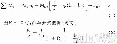
Ignore the quality of the axle, available
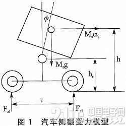
Where φ=Rφac, ac is the lateral acceleration received by the car when it starts to roll, also known as the car roll acceleration threshold; h is the distance from the center of gravity to the ground, hr is the distance from the center of the rollover to the ground; t is two Wheel spacing; Rφ represents the rollover stiffness, depending on the roll angle φ and the lateral acceleration ac. When ac reaches the maximum value, the car has a rollover, so φ and ac can be obtained in time. If measures are taken in time, the car can be prevented from rolling over.
2 system design
According to the above analysis, the vehicle rollover is mainly determined by parameters such as lateral acceleration, axial acceleration, track distance, and center of gravity to the ground. These parameters can be measured in real time and analyzed by the mechanical model of equation (1). Predict the running status of the car. For a given model of car, the height of the track and center of gravity to the ground can be considered as a known condition, so only the lateral acceleration and the axial acceleration need to be measured to calculate the operating state of the car.
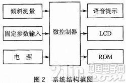
In this design, the acceleration measurement uses the dual-axis accelerometer ADXL203 to measure the axial and longitudinal acceleration of the vehicle in real time. Fixed parameters such as track, center of gravity to ground height, load weight, etc., using 4×4 membrane keyboard setting, the microcontroller uses MSP4 30F149 to receive and process the above input information in real time. In order to reduce the interference to the driver, the driver is prompted to take corresponding measures before the danger occurs. The LCD display uses a color LCD display to complete user input interaction. The memory records the state of the car for a period of time to facilitate user analysis. Power circuit, keyboard circuit and voice prompt, LCD and other modules use common circuit modules of electronic systems, which will not be described in this article. The system structure block diagram is shown in Figure 2.
3 tilt measurement circuit design
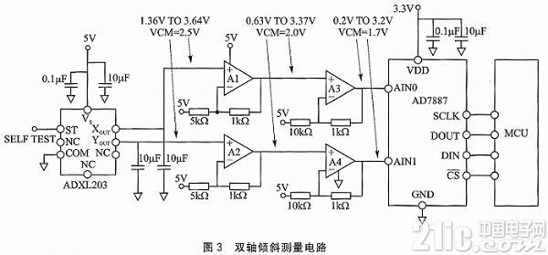
The tilt measurement circuit is the core of the vehicle anti-rollover warning circuit, which requires high-speed, accurate and real-time processing of the vehicle's driving attitude signal. The tilt measurement circuit is shown in Figure 3. According to the system design requirements, ADI's dual-axis accelerometer ADXL203 is used. It is a polysilicon surface micro-machining sensor with integrated signal conditioning circuit. X-axis or Y-axis during vehicle motion. The acceleration of the direction can be dynamically outputted with a corresponding voltage signal at the Xout or Yout end of the device.
Accelerometers work by using gravity as an input vector to determine the direction of an object in space. The sensor is a surface micromachined polysilicon structure placed on top of the wafer. The polysilicon spring is suspended above the structure on the wafer surface to provide acceleration force resistance.
The differential capacitor consists of a separate fixed plate and a movable mass connection plate that measures the deflection of the structure. The fixed plate is driven by a 180° anti-phase square wave, and the acceleration deflects the beam, making the differential capacitance unbalanced, so that the amplitude of the output square wave is proportional to the acceleration. The phase sensitive demodulation technique is then used to rectify the signal and determine the direction of the acceleration.
Due to the transient voltage signal output from the accelerometer, it is necessary to select a high performance op amp that runs fast and captures transient signals. Therefore, this paper selects the AD8608 four-channel op amp with low offset voltage, low bias current, low noise rail-to-rail input/output to achieve signal conditioning. A1~A4 in Figure 3 represent the four channels of AD8608.
After signal acquisition and conditioning are completed, it needs to be digitized and then input to the microcontroller for processing. The accuracy and speed of A/D conversion are the key factors. In order to process the data output by the accelerometer and calculate the angle, the output voltage of ADXL203 needs to be determined. Range and compare it to the ADC input voltage range.
The AD7887 has an input voltage range of 0 to 3.3 V. The ADXL203 has an ideal output voltage range of 1.5 to 3.5 V. Therefore, the circuit selects the high-speed low-power 12-bit SAR type A/D converter AD7887, which has a sampling rate of 125 ksps and a conversion operating frequency of 2.5 MHz.
The circuit can achieve an accuracy of 0.01 in the range of 90° inclination. The system is designed with low power consumption and small package size. Therefore, the circuit system has the characteristics of high precision, high performance, low cost and small size.
4 Experiment and result analysis
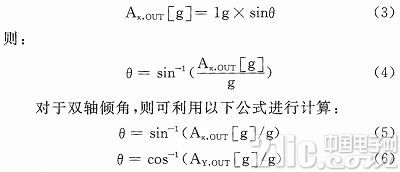
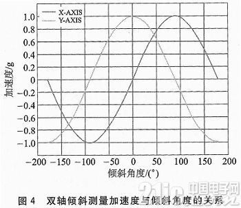
As shown in Figure 4, the gravity vector projection on the X-axis produces an output acceleration equal to the sine of the angle between the X-axis of the accelerometer and the horizontal plane. The horizontal plane is usually a plane orthogonal to the gravity vector. When the gravity is the ideal value of 1g, the output acceleration is:
Conclusion
The ADXL203 dual-axis accelerometer is used to collect the X-axis output and X-axis output of the vehicle running state signal in real time, and the signal is conditioned, converted and transmitted to the microcontroller. The mechanical theory model is used to analyze the parameters causing the vehicle rollover. The relationship, pre-judging the possibility of car rollover, and giving prompt information in a timely manner.
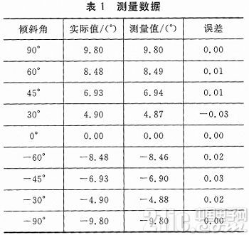
As listed in Table 1, the system has an angular measurement range of -90° to 90° and an error range of -0.03° to 0.03°, enabling high-precision measurement.
The system has the advantages of small size, low power consumption, good impact resistance and vibration resistance, and simple circuit structure, which can accurately measure the deflection angle of the rotating object, and can be widely applied to various inertial measurement systems, and has high application value.
Track Light Price,Outdoor Track Lighting,Commercial Track Lighting,Led Track Lighting Systems
Jiangmen Liangtu Photoelectric Technology Co., Ltd. , https://www.liangtulight.com