First, the overall design of the vehicle scheduling system:
This article refers to the address: http://
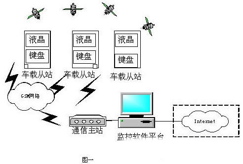
The entire system consists of four parts (1) the communication master station; (2) the vehicle slave station; and (3) the communication link. (4) System monitoring part. Let's take a brief introduction to the functions of each part.
(1) Communication master station: completes the forwarding of information, which is the link between the system monitoring part and the vehicle-mounted slave station, which forwards the information from the system monitoring part to the vehicle-mounted slave station. And receiving the information of the vehicle slave station, and uploading the information to the system monitoring part.
(2) Vehicle slave station: The monitored object receives the monitoring and dispatching command and can return its own status information. The acquisition of the status information relies on the GPS receiver in the in-vehicle slave station to perform the collection of the vehicle position and speed information and the like.
(3) Communication link: complete the information transmission of the communication master station and the vehicle slave station and the information interaction between the communication master station and the system monitoring portion. The former is based on the GSM mobile phone module as the communication tool in this design, while the latter is realized by RS232 or USB.
(4) System monitoring part: graphically displays the position information of the monitored vehicle on an electronic map (GIS, adoption of geographic information system), and can display text information such as its status. And the information of the scheduling command and the like can be input through the man-machine interface of the system monitoring part. Since the basic components of these vehicle monitoring systems are included in many papers, a brief introduction is given here. Related content can refer to the relevant paper materials. The following focuses on the kernel scheduling mechanism of UC/OS-II, the migration of operating systems, the development of embedded system programs based on state machines, and hardware design issues. Figure 1 shows a schematic diagram of the initial vehicle monitoring system.
Second, the kernel scheduling mechanism of the operating system:
Because the system is not very demanding, the UC/OS-II is a simple source code development operating system. Since UC/OS-II is scheduled based on tasks. Therefore, the intermediate results to be processed in the system or the response to external inputs and outputs should be completed in the task. The scheduling of tasks is based on priority (UC/OS does not support time slice rotation). After multitasking scheduling begins, the clock tick begins to work, the clock tick produces periodic interrupts, and the clock tick provides the basis for delay or timeout. Initialization should be done before multitasking, including CPU, TCB (task control block), ECB (event control block), and initialization of the operating system itself. After the initialization is completed, multitasking starts, and the system always runs the task with the highest priority in the ready state. Since the task itself is an infinite loop, the task must include functions that cause task switching, such as OSTimeDly(), OSSemPend(), etc. Execution to these functions will cause the task to be switched, that is, the scheduling of the task. The site should be protected before the task is switched. There are many ways to communicate between tasks, and there are many ways to communicate. You can use some common methods such as global variables and shared storage areas. However, in the system using UC/OS-II, the communication between tasks is more semaphores and message mailboxes. Wait.
Third, the transplantation of the operating system:
To port the UC/OS-II operating system to the Samsung ARM7TDMI S3C44B0X, pay attention to the OSCtxSW() task switching function. The core of the task switching is to use the pop command to restore the work site of each task. Use the interrupt return instruction to change the pointer of the PC to achieve the purpose of task switching. It actually restores all of the processor's registers from the task stack and executes the interrupt return instruction. The actual porting is to use software to simulate the occurrence of an interrupt. The key issue in porting is how to construct the task stack and the stacking order when switching tasks. The task area stack initialization is mainly the contents of the stack after the simulation task is interrupted. Also worth noting is the function of the switch interrupt function OS_ENTERCRITICAL() and OS_EXIT_CRITICAL(). These two functions implement the protection of the contents of the critical section.
Fourth, the state machine based program design:
The software design of the whole system adopts the design method of task plus state machine. Since the operating system of UC/OS-II is adopted in the system, all event processing in the system adopts the task scheduling mode, and the task runs under the scheduling of the operating system. For each task, a state machine-based design method is used, and the event that causes a state to be transferred in the system may be a semaphore or other events. The following describes the relevant contents of the state machine.
The state machine can be thought of as a graph of states and transitions that describe the application's response to the received event.
Execution of the state machine: The state machine processes an event at a certain time and must complete the processing of the event and get the result before processing another event.
The state machine based program execution process is such that there is one or more state machine activity states at all times. If a state is active, then a transition from this state may be fired, causing an event to be executed and causing another state or state at the initial state to be active (the next state is in the initial state).
State Machine It is a sequence of states that describe the events of the state machine's objects during the life of the object and their response to those events. It can be understood that the state machine state machine is the state of the object and is transferred from one state to another under the action of the event.
Several basic concepts in the state machine:
1. State: A condition or condition in the lifetime of an object during which the object will satisfy certain conditions, perform certain activities, or wait for certain events.
2. An event is an explanation of a meaningful thing that occupies a certain position in time and space. The generation of an event in the state machine can cause a state transition.
3. A transition is a relationship between two states that indicates a certain action that an object performs in the first state and enters a second state when a particular event or particular condition is met.
Another problem that should be noted in the programming of embedded systems is the reentrant problem of functions. Reentrant functions can be called recursively and can be called by two or more processes at the same time. This requires compiling time. To provide an analog stack area for a reentrant function.
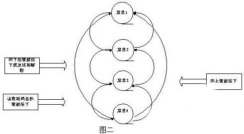
Figure 2 shows the LCD display in the system program designed using the state machine design method. The following is an explanation of Figure 2.
Menu 1 is to display the welcome interface (that is, the state mentioned above); menu 2 is to send a short message; menu 3 is to record the content of the short message; menu 4 is used to read the received short message. The specific state transition process is such that when the display is in the welcome interface, in this state, if the down button is pressed (this is an event) or the button for sending the short message is pressed, the system state transition Go to menu 2 (a state transition has occurred, the following is similar to this, so the corresponding analysis is omitted.); In this state, when the down button is pressed or the system wants to input the content of the short message, the system The status enters menu 3 from menu 2; in this state, when the downward keyboard is pressed, the state of the system shifts to menu 4; when the short message is read, the system state returns to the welcome screen. The actual system also has a return button, etc. Here is just a simple illustration of the programming method using the state machine.
Five, hardware design:
In order to take advantage of the high clock frequency of the S3C44B0X, reduce the delay of the S3C44B0X in fetching and accessing data, the system uses the code to be solidified in the FLASH, and the code is copied from the FLASH to the SDRAM after the system is started. And the system uses PDIUSBD12 as communication between the communication master station and the system monitoring part on the PC. Compared to the RS232 serial communication method, the speed has a large liquid increase. Especially when the number of scheduled vehicles is relatively large, the speed advantage is obvious.
Sixth, summary:
After the system is running, the system meets the design requirements.
Design concept: All new design elements, conforming to lighting engineering. Emitting soft and comfortable light, no strobe for better eye-sight. Longer life span, eco-friendly.
Users: Suitable for all kinds of persons to use. No matter you are a student or a white collar, you will like this natural and comfortable light.
1.Innovative design, combine the living color light and table lamp, more fashionable, convenient and useful.
2.Flexible goose neck lamp arm, illuminate a super wide angle.
3.Eco-friendly, mercury free, radiation free.
4.Eye-protection: uniform and soft light effect, anti-dazzle, relieve visual fatigue.
Gift Desk Lamp,3D Gift Desk Lamp,LED Gift Desk Lamp,Acrylic Gift Desk Lamp,Smart Desk Lamp
Shenzhen Superlight Technology Co., Ltd. , https://www.superlighttech.com