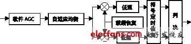
In recent years, various technologies of PCs have been rapidly developed, and the computing speed and memory capacity of CPUs have been greatly improved. The digital signal processing capability has fully met the real-time demodulation of conventional communication signals. Designing the modem on the sound card instead of the DSP chip has many advantages: First, the sound card is cheap and easy to get, and the port in line, mic in, line out, spk out and other ports on the card can be fully utilized to realize real-time solution of multi-channel signals. Tune, one card is used more; Secondly, the optimized demodulation software takes up less time of CPU, and can do other work while receiving data; third, it is not limited by storage space, programming with high-level language, and the design cycle is short. In addition, this design scheme has nothing to do with the hardware platform, and the software upgrade period is short. This article is based on this idea, throwing away the DSP device, using PC as the hardware platform to realize real-time demodulation of QPSK signal. The system block diagram is shown in Figure 1.

In Figure 1, the baseband signal output by the receiver is sampled by a PC sound card to obtain a discretized digital sequence. The sampling of the signal can be controlled by the API function of Windows, including the sampling frequency, the size of the buffer, the number of bytes read in each time, etc. For specific implementation, refer to related materials, and no further description is provided herein. The demodulation software part of Figure 1 is the focus of this paper. It completes the digital real-time demodulation function of the signal. The digital demodulation principle is shown in Figure 2.
Software AGC
Software AGC is used to track signal outsourcing changes to compensate for fading. This paper uses the logarithmic AGC shown in Figure 3.
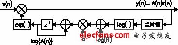
When the logarithmic AGC in Fig. 3 is implemented in software, the calculation of A(n) adopts the following formula.
Log{A(n+1)}=log{A(n)}+α[log{R}-log{|A(n)x(n)|}]
In the figure, x(n) is the input signal of software AGC, y(n) is the output signal; A(n) is the gain control variable of AGC; α and R are constant, and the value is based on the design requirements in the compensation speed and stability. In the case of a compromise, when the compensation speed is required to be fast, a larger value is taken, and conversely, a smaller value is taken.
DFPLL carrier frequency recovery
Near the bit sync point, there is a crosstalk problem between the signals. The basic idea of ​​DFPLL is to calculate the phase of the symbol by using the sampling points near the bit synchronization for each symbol, and calculate the difference between the reference carrier and the signal carrier according to the phase characteristics of the baseband signal symbol, and use the difference. Adjust the phase of the VCO for carrier recovery.
Let the phase information of the nth symbol of the QPSK signal at the bit synchronization point be: where i=0, 1, 2, 3, θ(n) is the phase offset of the nth symbol. To obtain the phase error, it is necessary to remove the information component πi/2 in the phase information. By observing the QPSK constellation diagram, it can be found that the phase difference between adjacent constellation points is always around π/2, so the information component can be removed by the following method. Let, and let, where mod denotes the remainder and ξ(n) is the phase error of a single symbol. If the sampling frequency is Fs and the symbol rate is fb, the average phase error of each sample point of the symbol is e(n)=ξ(n)/(Fs/fb). The average phase error is sent to the loop filter. The filtered result is adjusted by the coefficient k and sent to the VCO for phase increment adjustment. When e(n) is stable near a small value, the DFPLL is locked. The loop filter uses a first-order RC low-pass filter. Since the input is a phase estimator, considering that the phase difference signal from the phase estimator changes at the symbol rate fb, the cutoff frequency should be near fb, and the normalized system function is designed by the impulse invariant method. The cutoff frequency and gain k of the filter have an effect on the capture time and the stability of the loop. These two parameters are adjusted to achieve the best condition.
Commercial Coffee Urn,Coffee Urn,100 Cup Coffee Urn,Large Coffee Urn
FOSHAN FORTUNE ELECTRICAL APPLIANCE CO.,LTD , https://www.coffelady.com