Based on the project practice of car door control module design, this paper introduces a high-performance smart power chip TLE7810, and elaborates its application in low-cost electric vehicle controller from software and hardware. Finally, the anti-pinch function of the electric window and its implementation method are briefly introduced.
Keywords smart power chip TLE7810 anti-pinch
This article refers to the address: http://
With the increasing popularity of automobiles, consumers' demands for car comfort are also increasing. More and more cars are beginning to choose the power window control system that uses the microcontroller as the core. The continuous development of semiconductor technology and embedded systems in the past decade has enabled manufacturers to meet consumers' demands for the safety and comfort of electric window shakers at a lower cost. The use of single-chip controlled electric windows can realize the identification and protection of various states of the door. In addition, the use of single-chip microcomputer can carry out pulse width modulation (PWM), the use of PWM motor drive mode can extend the life of the motor, and improve the performance of the window lift, reduce operating noise. Network bus systems such as CAN and LIN enable the modular design of the car and the interactive communication between the modules.
Today, a new generation of smart power devices is quietly emerging. This kind of power device combines the control function of the single chip microcomputer and the driving capability of the power device. On the one hand, the production and design cost of the controller are reduced, on the other hand, the circuit is more compact, and the electromagnetic compatibility performance of the controller is improved. Based on the project practice of automobile door control module design, this paper introduces a low-cost power window hardware and software design based on smart power chip TLE7810, and introduces the anti-pinch function of electric window.
1 Overall design of the door control module Figure 1 is a block diagram of the car door control module. The intelligent power device TLE7810 integrates an 8-bit microcontroller, a power device and a LIN bus driver. The two low-side switches of the TLE7810 can be used to control the primary coil of the relay, which in turn controls the H-bridge of the relay to achieve forward and reverse rotation of the motor, ie controlling the rise and fall of the window. On the other hand, the PWM signal generated by the single-chip microcomputer can control the fast-on and off of the insulated gate field effect transistor (MOSFET) connected to the grounding end of the window motor circuit, thereby controlling the on and off of the motor circuit, avoiding the time when the motor is just starting. Full load operation, also known as motor soft start, while achieving voltage PwM control. In addition, the current sensor and Hall effect sensor can also feedback the running state and running position of the motor to the MCU in time to ensure the robustness of the system operation (see Figure 3).

2 hardware design of electric windows
2.1 Logic Control and External Communication The power device TLE7810 integrates an 8-bit microcontroller chip, a power device chip and a LIN bus driver chip. Because the TLE7810 has such a highly integrated structure, it has almost assumed all the logic control and circuit drive tasks of the entire controller. The TLE7810 has a total of 28 pins that are internally connected via a synchronous serial port (SPI).
The 8-bit MCU embedded in the TLE7810 is based on the standard 8051 architecture. It adds system peripherals and improves the computing power of the processor. It can sample the motor current, battery voltage and other signals in real time, receive fault signals and judge the window operation. status. The MCU sends commands to the power device through the high-speed SPI, and receives diagnostic information from the power device. At the same time, the asynchronous serial communication interface of the single chip microcomputer is connected to the LIN driver chip of the power device, and then connected with the external LIN bus, and communicates with other modules to ensure driving safety.
The power devices inside the TLE7810 are very powerful and include:
â—†The driving power of the single chip microcomputer and the Hall sensor;
â—† Receive SPI instruction from MCU, control the action of two low-side switches and one high-side switch, and return diagnostic information through SPI;
â—† five-way wake-up input;
â—† Watchdog timer that controls the reset of the microcontroller;
â—†temperature / power voltage sensor;
â—†LIN driver chip.
2.2 Power chip driver circuit Figure 2 shows the external circuit of the TLE7810. VS is the supply voltage sampling input port. The TLE7810 integrates a 1:8 operational amplifier circuit that can sample A/D voltages between 0 and 40 V. Port MON5 is a high-side switch that can be used as a driving power source for the LED to indicate the controller's operating state. Ports MON1, MON2, MON3, and MON4 are connected to buttons that control the operation of the window. In some states, the TLE7810 will enter a low-power sleep mode, and these buttons will wake up the system.

2.3 Motor drive circuit Figure 3 is the motor drive circuit of the window controller. Since the current output from the TLE7810 is not sufficient to directly drive the window motor, the low-side switch of the TLE7810 drives the relay, and the H-bridge composed of the relay operates the window to rise or fall. A MOS-FET is connected in series at the ground of the relay, and the PWM waveform control generated by the comparison module is captured by the 8-bit single-chip microcomputer, which can realize the soft start of the motor, improve the running performance of the motor and prolong the service life of the motor.

2.4 Motor speed and current sampling In the low side of the H-bridge of the control motor, an O. 01Ω sampling resistor, the voltage of the sampling resistor is connected to the A/D conversion input port of the single-chip microcomputer through an operation amplification circuit with a magnification ratio of 21 times to detect the current when the motor is running, and to identify the stall, open circuit and short circuit of the motor. . Since the accuracy of the A/D converter inside the TLE8710 is 10 bits, the corresponding current is calculated as follows:
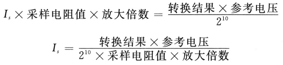
Therefore, assuming that the motor stall current is 10 A and the reference voltage is 5 V, when the sampling result is greater than 430, it can be considered that the motor has stalled. For the purpose of protecting the motor, the program will automatically turn off the power and the motor will enter the coasting state.
In addition, in order to achieve the anti-pinch function of the window, the controller uses a double Hall sensor TLE4966 to determine the position of the window and the motor speed. A magnetic ring with a diameter of about 2 cm is mounted on the upper end of the rotor shaft of the motor. The window board of the window controller is designed like a pistol. There is a protruding part about 3 cm long on the lower side of the PCB board, and a Hall sensor is placed at the top for inserting into the motor so that the magnetic ring can be placed close to the magnetic ring. The Hall effect is used to measure the position and speed of the motor. When the motor rotates, the magnetic ring also produces an alternating magnetic field. Each time the rotor rotates, the Hall sensor outputs a periodic square wave signal. The comparison capture module of the MCU generates an interrupt when the falling edge of the Hall signal arrives, and records the value of the time register at this time. By using the difference between the two values ​​before and after, the cycle of the square wave signal can be calculated, thereby obtaining the motor rotation speed. .
Due to the high integration and specificity of the TLE7810, the entire system circuit is simple and reliable. The number of chips used here is extremely small, and the EMC performance of the controller is greatly improved.
3 The software design of the power window uses a 16-bit timer with automatic reload function as the main timer. The timer overflows every 20 ms, and the interrupt service routine sets the 20 ms flag. In the main program, the MCU constantly polls the timer flag and periodically performs tasks such as A/D sampling, scan command port, call motor control function, and LIN communication.
3.1 Control of the window motor As shown in Figure 4, after the initialization of the program is completed, the motor enters the off state. After the button port scans to the control command for the rising (or falling) button input, the main program calls the motor control function and the motor enters the PWM soft start. The PWM startup is divided into 10 steps, each step is 20 ms, and the duty cycle is gradually increased from 10% to 100%. The motor then enters a rising (or falling) state. If the controller receives a stop, fall (or rise) command or a stall, the motor enters the 200 ms inertia braking phase, at which time the PWM duty cycle is zero and the MOSFET is turned off. After this phase is over, the motor enters a rising (or falling) stop state. If the button is stopped, lowered (or raised) at this time, the motor enters the shutdown state.

If the sampling current exceeds the limit value of the short-circuit protection during the rising (or falling) process, it is considered that a short-circuit fault occurs at this time, and the motor will directly enter the rising (or falling) stop state to prevent the motor from being burnt due to excessive current. .
If the current is much lower than the normal running current during the running of the motor, it can be judged that an open circuit fault has occurred. This information will be fed back to the host computer through the LIN bus, thus facilitating the diagnosis and elimination of the fault.
3.2 Window anti-pinch function In order to prevent the accident of pinching passengers when the window is automatically raised. The anti-pinch function is designed in the controller. When the window glass runs in the anti-pinch area (200 to 4 mm from the top), the program calculates the motor speed based on the signal from the Hall sensor to determine if the window is facing an obstacle. If an obstacle is encountered, a falling command is issued to implement the protection function. The results of the anti-pinch experiment are shown in Figure 5.

Conclusion The power window controller uses Infineon's new generation of intelligent power devices, making full use of on-chip resources, reducing system design and production costs. The controller's short circuit, open circuit detection function and anti-pinch function also improve the driving comfort, improve the reliability of the system and ensure the safety of driving.
iPad 2 Protector Case, iPad 3 Protector Case, Tablet PC Protector Case
BETOP TECHNOLOGY CO.,LTD , http://www.betopparts.com